
Concept explainers
Videos
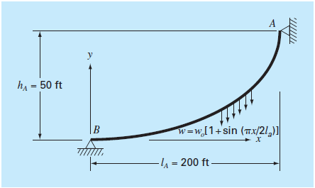
A cable is hanging from two supports at A and B (Fig. P28.25). The cable is loaded with a distributed load whose magnitude varies with x as
where
Solve this equation using a numerical method and plot the shape of the cable
Want to see the full answer?
Check out a sample textbook solution
Chapter 28 Solutions
EBK NUMERICAL METHODS FOR ENGINEERS
Additional Engineering Textbook Solutions
Basic Technical Mathematics
Advanced Engineering Mathematics
Fundamentals of Differential Equations (9th Edition)
Statistical Reasoning for Everyday Life (5th Edition)
College Algebra & Trigonometry - Standalone book


- The graph shown below shows the Modulus of Elasticity (E) of different materials with respect to temperature (°C). 240 210 170 140 100 -Carbon Steel, C < 0.3% -Nickel Steels, Ni 2% - 9% 70 Cr-Mo Steels, Cr 2%-3% Copper -Leaded Ni-Bronze -Nickel Alloys - Monel 400 35 -Titanium rengineeringtoolbox.com -Aluminium -300 -200 -100 100 300 400 500 600 700 800 Temperature (degc) a) Which material is the most ductile with increasing temperature? b) Which material is the least ductile with increasing temperature? c) Discuss the change in ductility (brittle / ductile behavior) occurring for different materials. Also, comment on why Young's modulus changes with temperature. E-modulus of elasticity (GPa)arrow_forwardThe following related values of the pressure p in kN/m2 and the volume V in cubic meter where measured from the compression curve of an internal combustion engine indicator diagram. Assuming that P and V are connected by the law PVn: C, find the value of n. p 3450 2350 1725 680 270 130 V .0085 .0113 .0142 .0283 .0566 .0991arrow_forward5251 (S122) Mechanics X PowerPoint Presentation x Slide 1 X Final exam (Remotely Procto e.uowplatform.edu.au/mod/quiz/secured.php#lockdown 1 Gmail Question 1.14 A pipe with a hollow circular cross-section, as shown in Figure Q1.14, is in torsion. The shear stress is maximum for a position p, measured from the centre of the cross section. p equals to on Figure Ql.14 5 O a. r₁ O b. (r₁+r2)/2 O c. 12 O d. shear stress is constant Question 1.15 Considering the stress state represented in Figurarrow_forward
- Jquizzes/332866/take/questions/4602486 B 20° 10° A 500 N A 100% EGION 2.arrow_forwardELASTICITY OF A RUBBER BANO Weight (F) Initial length (li)cm kength with load (l2)um |Elongation x) x= l2 -l 20g 子62cm 8.25 am 0.63 40g 7.7 cm 8.89 cm 1.19 60g チ19 cm 9.22 cm 1.32 l:95 80g 100g 7.9 cm チ4 cm cm. 10.5 om 2e 6 Draw a straight line through mean of the points plo Hed and determine the slope a. Plot F against x(the x-axis), the Giraph: Legend. (Blue) Rubber bandarrow_forwardSection 1.5 Problem 1. Mark each statement True or False, and justify your answer. (T/F) A homogeneous equation is always consistent. (T/F) If x is a nontrivial solution of Ax=0, then every entry in x is nonzero. (T/F) The equation Ax=0 gives an explicit description of its solution set. (T/F) The equation x = xu+xiv, with xa and xx free (and neither u nor va multiple of the other), describes a plane through the origin. (T/F) The homogeneous equation Ax=0 has the trivial solution if and only if the equation has at least one free variable. (T/F) The equation Ax=b is homogeneous if the zero vector is a solution. (T/F) The equation x = p + tv describes a line through v parallel to p. (T/F) The effect of adding p to a vector is to move the vector in a direction parallel to p.arrow_forward
- ull JAWWAL ? 6:20 PM @ 50% A moodle.najah.edu МOODLE Recent - For the following system, answer the following assuming each tension in cable = 10 kN 1) Express tensions in Cartesian coordinate system 2) Find moment due to both cables and weight of door= 1 kN about point A 3) Find moment due to both cables and weight of door= 1 kN about z-axis 960 mm 450 mm 90 mm 675 mm B 90 mm 690 mm 270 mm Fig. P4.113 IIarrow_forward100 80 60 40 20 0.002 0.004 0.006 0.008 0.01 0.012 Strain, in/in. FIGURE P1.17 1.18 Use Problem 1.17 to graphically determine the following: a. Modulus of resilience b. Toughness Hint: The toughness (u) can be determined by calculating the area under the stress-strain curve u = de where & is the strain at fracture. The preceding integral can be approxi- mated numerically by using a trapezoidal integration technique: u, = Eu, = o, + o e, - 6) %3D c. If the specimen is loaded to 40 ksi only and the lateral strain was found to be -0.00057 in./in., what is Poisson's ratio of this metal? d. If the specimen is loaded to 70 ksi only and then unloaded, what is the permanent strain? Stress, ksiarrow_forward122 1.17 The tripod shown in Fig. 1.73 is used for mounting an electronic instrument that finds the distance between two points in space. The legs of the tripod are located symmetrically about the mid-vertical axis, each leg making an angle a with the vertical. If each leg has a length / and axial stiffness k, find the equivalent spring stiffness of the tripod in the verti- cal direction. CHAPTER 1 FUNDAMENTALS OF VIBRATION FIGURE 1.73 A tripod carrying an electronic instrument.arrow_forward
- 2. In class, we derived an expression for hR/RT for a gas that obeyed the Pressure Explicit Virial Expansion truncated after the third term. In class, we assumed that B and C were not functions of temperature. a. Please rework the derivation with B = B(T) and C = 0. b. Please continue the derivation under the assumption that B(T) = mT + b. Where m and b are the slope and y-intercept of a straight, respectively. %3Darrow_forwardThe mass attached to the end of a helical pull spring statically forces the spring to pull, and 100 mm static elongation in the spring references The same mass is attached to the end of this spring, and the mass is released vertically from a height of 0.6 meters how many times does the force on the spring increase according to the static loading state when it is released? 4.32 O 4.87 5.36 5.12 18110140 O 4.60arrow_forwardA thin flexible gold chain of uniform linear density has a mass of 17.5 g. It hangs between two 30.0 cm long vertical sticks (vertical axes) which are a distance of 30.0 cm apart horizontally (x-axis), as shown in the figure below which is drawn to scale. Evaluate the magnitude of the force on the left hand pole. 30 28 26 24 22 20 18 16 14 12 10 8 6 4 2 0 0 2 4 6 58 10 12 14 16 18 20 22 24 26 28 30arrow_forward
 Elements Of ElectromagneticsMechanical EngineeringISBN:9780190698614Author:Sadiku, Matthew N. O.Publisher:Oxford University Press
 Mechanics of Materials (10th Edition)Mechanical EngineeringISBN:9780134319650Author:Russell C. HibbelerPublisher:PEARSON
 Thermodynamics: An Engineering ApproachMechanical EngineeringISBN:9781259822674Author:Yunus A. Cengel Dr., Michael A. BolesPublisher:McGraw-Hill Education
 Control Systems EngineeringMechanical EngineeringISBN:9781118170519Author:Norman S. NisePublisher:WILEY
 Mechanics of Materials (MindTap Course List)Mechanical EngineeringISBN:9781337093347Author:Barry J. Goodno, James M. GerePublisher:Cengage Learning
 Engineering Mechanics: StaticsMechanical EngineeringISBN:9781118807330Author:James L. Meriam, L. G. Kraige, J. N. BoltonPublisher:WILEY