
Videos
Consider the class−AB MOSFET output stage shown in Figure P8.46. The circuit meters are
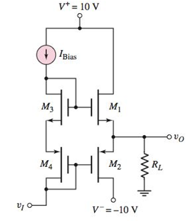
Figure P8.46
Want to see the full answer?
Check out a sample textbook solution
Chapter 8 Solutions
Microelectronics: Circuit Analysis and Design


- Since IDSS=8 mA, VGS(off) = -10V according to the circuit on the side, if the capacitor C2 is removed, what will be the Av gain value?arrow_forward2. a) Design a 9v DC oscillator circuit that produces a frequency of 500 Hz. The circuit may use a 555 timer or two transistor design(s). Show all calculations including the DC currents and bias voltages. Include the schematic and the required frequency formula(s). b) As a bonus, if a larger load were required to be connected to the chip, how would the schematic look and what components would be used to do design it? Also, as a theoretical approximation, if the 9v battery had a rating of 4 amp-hours, how long would it last powering this circuit? Show calculations to illustrate how you arrived at the answer.arrow_forwardDraw the Nyquist plot for the system in the figure below. Using the Nyquist stability criterion, determine the range of K for which the system is stable. Consider both positive and negative values of K.( Need only handwritten solution please otherwise downvote)arrow_forward
- Ex. 1780. A closed-loop system has sustained oscillations (i.e. constant amplitude) with a period of 85 seconds when the gains are: proportional=96, integral=0, and derivative=0. Determine the ideal- PID gains Kp, Ki (minutes^-1), Kd (minutes) using the Ziegler-Nichols method. Also determine the standard-PID values which are commonly used in industry, such as LabVIEW: Kc, Ti (min), Td (min). ans:6arrow_forwardThe ac equivalent circuit for an amplifier is shown. Assume the capacitors have infinite value, RI =750Ω, RB =100 kΩ, RC =100 kΩ, and R3 =100 kΩ. Calculate the input resistance and output resistance for the amplifier if the BJT Q-point is (75 μA, 10 V). Assume βo =100 and VA =75 V.arrow_forwardWhen the ltspice simulation of the circuit shown in the figure is performed, the output voltage (Vout) is obtained as given in which of the figures below? NOTE-1: Vcc = 12 V, RC = 2.2 kΩ, RB = 15 kΩ, RE = 180 Ω and C1 = 1 μF. NOTE-2: For the input voltage Vin, the DC offset voltage is 1.6 V, while the applied sinusoidal signal has a amplitude of 10 mV and a frequency of 10 kHz.arrow_forward
- Q 3 Bring out the advantages and disadvantages of microwave tube devices andsemiconductor devices.What are the most common types of microwave diodes and transistors in use give theirbasic features features and applications?What are the most common types of microwave ICs? Give details of the circuit elementsand applicationsarrow_forwardIn the context of MOS devices, state briefly the advantages of:(a) constant field scaling(b) high-κ dielectrics(c) mid-gap metalsarrow_forwardThe ac equivalent circuit for an amplifier is shown . Assume the capacitors have infinite value, RI = 10 kΩ, RG = 1 MΩ, RD = 3.9 kΩ, and R3 = 33 kΩ. Calculate the voltage gain for the amplifier if the MOSFET Q-pointis (2 mA, 7.5 V). Assume Kn = 1 mA/V2 and λ = 0.015 V−1.arrow_forward
- Describe the combined effect of the RC circuits for higher frequency response in a BJT & FETamplifier. the subject : Analogue Electronics IIarrow_forwardGiven: Voltage Divider Bias Circuit Supply: 10Vdc to 24Vdc Load: 1000 ohms Voltage Gain: 80 to 400 Lower Cutt off Frequency: 100Hz Sinusoidal source (zero internal resistance): 50mVp-p Transistor: Si, beta=75 Base-Collector Capacitance= 8pF Base-Emitter Capacitance= 25pF Design a Single-stage Common Emitter Class A Amplifier and compute the following: a) dc load line b) hie c) midband gain d) Miller equivalent Capacitances e) upper cut off frequencyarrow_forwardThe ac equivalent circuit for an amplifier is shown . Assume the capacitors have infinite value, RI = 750 Ω, RB = 100 kΩ, RC = 62 kΩ, and R3 = 100 kΩ. Calculate the voltage gain and input resistance for the amplifier if the BJT Q-point is (40μA, 10 V). Assume βo = 100 and VA = 75V.arrow_forward
 Introductory Circuit Analysis (13th Edition)Electrical EngineeringISBN:9780133923605Author:Robert L. BoylestadPublisher:PEARSON
 Delmar's Standard Textbook Of ElectricityElectrical EngineeringISBN:9781337900348Author:Stephen L. HermanPublisher:Cengage Learning
 Programmable Logic ControllersElectrical EngineeringISBN:9780073373843Author:Frank D. PetruzellaPublisher:McGraw-Hill Education
 Fundamentals of Electric CircuitsElectrical EngineeringISBN:9780078028229Author:Charles K Alexander, Matthew SadikuPublisher:McGraw-Hill Education
 Electric Circuits. (11th Edition)Electrical EngineeringISBN:9780134746968Author:James W. Nilsson, Susan RiedelPublisher:PEARSON
 Engineering ElectromagneticsElectrical EngineeringISBN:9780078028151Author:Hayt, William H. (william Hart), Jr, BUCK, John A.Publisher:Mcgraw-hill Education,