
Microelectronics: Circuit Analysis and Design
4th Edition
ISBN: 9780073380643
Author: Donald A. Neamen
Publisher: McGraw-Hill Companies, The
expand_more
expand_more
format_list_bulleted
Videos
Textbook Question
Chapter 8, Problem 8.17P
Consider the class−A source−follower circuit shown in Figure P8.17. The transistors are matched with parameters
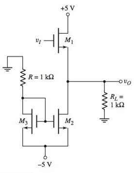
Figure P8.17
Expert Solution & Answer
Want to see the full answer?
Check out a sample textbook solution
Students have asked these similar questions
Describe the combined effect of the RC circuits for higher frequency response in a BJT & FETamplifier.
the subject : Analogue Electronics II
What is Maximum Usable Frequency (MUF)? Derive the expression of MUF critical frequency (fcr) and skip distance assuming curve earth.
What is the typical response time for MOV's?
Chapter 8 Solutions
Microelectronics: Circuit Analysis and Design
Ch. 8 - Prob. 8.1EPCh. 8 - Prob. 8.2EPCh. 8 - Prob. 8.3EPCh. 8 - Prob. 8.1TYUCh. 8 - Prob. 8.2TYUCh. 8 - Prob. 8.3TYUCh. 8 - Prob. 8.4EPCh. 8 - Prob. 8.5EPCh. 8 - Prob. 8.7EPCh. 8 - Prob. 8.4TYU
Ch. 8 - Prob. 8.5TYUCh. 8 - Prob. 8.6TYUCh. 8 - A transformercoupled emitterfollower amplifier is...Ch. 8 - Prob. 8.7TYUCh. 8 - Prob. 8.9EPCh. 8 - Prob. 8.11EPCh. 8 - Consider the classAB output stage shown in Figure...Ch. 8 - From Figure 8.36, show that the overall current...Ch. 8 - Prob. 1RQCh. 8 - Describe the safe operating area for a transistor.Ch. 8 - Why is an interdigitated structure typically used...Ch. 8 - Discuss the role of thermal resistance between...Ch. 8 - Define and describe the power derating curve for a...Ch. 8 - Define power conversion efficiency for an output...Ch. 8 - Prob. 7RQCh. 8 - Describe the operation of an ideal classB output...Ch. 8 - Discuss crossover distortion.Ch. 8 - What is meant by harmonic distortion?Ch. 8 - Describe the operation of a classAB output stage...Ch. 8 - Describe the operation of a transformercoupled...Ch. 8 - Prob. 13RQCh. 8 - Sketch a classAB complementary MOSFET pushpull...Ch. 8 - What are the advantages of a Darlington pair...Ch. 8 - Sketch a twotransistor configuration using npn and...Ch. 8 - Prob. 8.1PCh. 8 - Prob. 8.2PCh. 8 - Prob. 8.3PCh. 8 - Prob. 8.4PCh. 8 - Prob. 8.5PCh. 8 - Prob. D8.6PCh. 8 - A particular transistor is rated for a maximum...Ch. 8 - Prob. 8.8PCh. 8 - For a power MOSFET, devcase=1.5C/W , snkamb=2.8C/W...Ch. 8 - Prob. 8.10PCh. 8 - The quiescent collector current in a BiT is ICQ=3A...Ch. 8 - Prob. 8.12PCh. 8 - Prob. 8.13PCh. 8 - Prob. 8.14PCh. 8 - Prob. 8.15PCh. 8 - Prob. 8.16PCh. 8 - Consider the classA sourcefollower circuit shown...Ch. 8 - Prob. 8.18PCh. 8 - Prob. 8.19PCh. 8 - Prob. 8.20PCh. 8 - Prob. 8.21PCh. 8 - Consider an idealized classB output stage shown in...Ch. 8 - Consider an idealized classB output stage shown in...Ch. 8 - Prob. 8.24PCh. 8 - For the classB output stage shown in Figure P8.24,...Ch. 8 - Prob. 8.26PCh. 8 - Prob. 8.27PCh. 8 - Consider the classAB output stage in Figure P8.28....Ch. 8 - Prob. 8.29PCh. 8 - Prob. D8.30PCh. 8 - Prob. 8.31PCh. 8 - Prob. D8.32PCh. 8 - Consider the transformercoupled commonemitter...Ch. 8 - The parameters for the transformercoupled...Ch. 8 - A BJT emitter follower is coupled to a load with...Ch. 8 - Consider the transformercoupled emitter follower...Ch. 8 - A classA transformer-coupled emitter follower must...Ch. 8 - Repeat Problem 8.36 if the primary side of the...Ch. 8 - Consider the circuit in Figure 8.31. The circuit...Ch. 8 - Prob. D8.40PCh. 8 - The value of IBiass in the circuit shown in Figure...Ch. 8 - The transistors in the output stage in Figure 8.34...Ch. 8 - Consider the circuit in Figure 8.34. The supply...Ch. 8 - Prob. 8.44PCh. 8 - Prob. 8.45PCh. 8 - Consider the classAB MOSFET output stage shown in...Ch. 8 - Prob. 8.47PCh. 8 - Consider the classAB output stage in Figure P8.48....Ch. 8 - For the classAB output stage in Figure 8.36, the...
Knowledge Booster


Learn more about
Need a deep-dive on the concept behind this application? Look no further. Learn more about this topic, electrical-engineering and related others by exploring similar questions and additional content below.Similar questions
- Apply the knowledge gained from the ac analysis of BJT to construct the AC equivalent model of the circuit shown in Figagure and calculate Zo and Av. Given, β = ( 79 × 10) and ro = 79 kΩarrow_forwardThe circuit as shown is called a quadrature oscillator. Derive an expression for its frequency of oscillation. What value of RF is required for sinusoidaloscillation (in terms of R)?arrow_forwardConsider the topic LEDs. (a) Explain the working principle of LEDs by using energy band diagram (spontaneous emission), (b) Explain the difference between AMOLEDs and PMOLEDs, (c) Give examples of materials to be used as LEDs with their band gap magnitude. Optoelectronicsarrow_forward
- Since IDSS=8 mA, VGS(off) = -10V according to the circuit on the side, if the capacitor C2 is removed, what will be the Av gain value?arrow_forwardIf the frequency that is injected into an AM modulator is 100Mhz and it is combined with another injected signal of 10Khz, we can say that the combination is:arrow_forwardif the parameters for the BJT given Beta=120, VBE=0.7V, VT=26mV, VA=infinityarrow_forward
- The topic is about BJT DC Analysis. Please show the correct and complete solution to this problem. Thank you!arrow_forwardIn a particular UJT, rB1 = 20 kohms and r82 = 15 kOhms. Therefore, its intrinsic standoff ratio is?arrow_forwardA subcarrier given in Eq. 4.1 is amplitude modulated by an information signal given in Eq. 4.2. The resulting AM signal is then used to amplitude modulate the signal given in Eq. 4.3 to generate a signal that is finally transmitted. Derive a mathematical expression for this final signal that is transmitted. How, in practice, can this system be made with minimum harmonic distortion? Equations for Question 04arrow_forward
arrow_back_ios
SEE MORE QUESTIONS
arrow_forward_ios
Recommended textbooks for you
 Introductory Circuit Analysis (13th Edition)Electrical EngineeringISBN:9780133923605Author:Robert L. BoylestadPublisher:PEARSON
 Delmar's Standard Textbook Of ElectricityElectrical EngineeringISBN:9781337900348Author:Stephen L. HermanPublisher:Cengage Learning
 Programmable Logic ControllersElectrical EngineeringISBN:9780073373843Author:Frank D. PetruzellaPublisher:McGraw-Hill Education
 Fundamentals of Electric CircuitsElectrical EngineeringISBN:9780078028229Author:Charles K Alexander, Matthew SadikuPublisher:McGraw-Hill Education
 Electric Circuits. (11th Edition)Electrical EngineeringISBN:9780134746968Author:James W. Nilsson, Susan RiedelPublisher:PEARSON
 Engineering ElectromagneticsElectrical EngineeringISBN:9780078028151Author:Hayt, William H. (william Hart), Jr, BUCK, John A.Publisher:Mcgraw-hill Education,
Introductory Circuit Analysis (13th Edition)
Electrical Engineering
ISBN:9780133923605
Author:Robert L. Boylestad
Publisher:PEARSON
Delmar's Standard Textbook Of Electricity
Electrical Engineering
ISBN:9781337900348
Author:Stephen L. Herman
Publisher:Cengage Learning
Programmable Logic Controllers
Electrical Engineering
ISBN:9780073373843
Author:Frank D. Petruzella
Publisher:McGraw-Hill Education
Fundamentals of Electric Circuits
Electrical Engineering
ISBN:9780078028229
Author:Charles K Alexander, Matthew Sadiku
Publisher:McGraw-Hill Education
Electric Circuits. (11th Edition)
Electrical Engineering
ISBN:9780134746968
Author:James W. Nilsson, Susan Riedel
Publisher:PEARSON
Engineering Electromagnetics
Electrical Engineering
ISBN:9780078028151
Author:Hayt, William H. (william Hart), Jr, BUCK, John A.
Publisher:Mcgraw-hill Education,
Diode Logic Gates - OR, NOR, AND, & NAND; Author: The Organic Chemistry Tutor;https://www.youtube.com/watch?v=9lqwSaIDm2g;License: Standard Youtube License