
Concept explainers
(a)
The value of
(a)
Answer to Problem 8.9EP
The value of the bias current is
Explanation of Solution
Calculation:
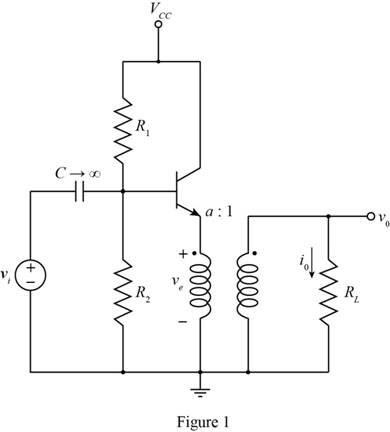
The given diagram is shown in Figure 1
The conversion from
The expression for the value of the base to emitter to voltage is given by,
Substitute
The expression for the bias current is given by,
Substitute
Conclusion:
Therefore, the value of the bias current is
(b)
The value of
(b)
Answer to Problem 8.9EP
The value of current
Explanation of Solution
Calculation:
The value of peak voltage and output voltage are equal and the expression for the value of the load current is given by,
Substitute
The expression for the emitter current for3 the
Substitute
The expression for the base current of the
Substitute
The expression for the collector current of
Substitute
The conversion from
The conversion from
The conversion from
The expression to determine the value of the diode current is given by,
Substitute
The value of the collector current for
Substitute
The expression for the base emitter voltage of
Substitute
The expression for the value of
Substitute
The expression for the base emitter voltage of
Substitute
The expression for the collector current
Substitute
Conclusion:
Therefore, the value of current
(c)
The value of
(c)
Answer to Problem 8.9EP
The value of current
Explanation of Solution
Calculation:
The value of peak voltage and output voltage are equal and the expression for the value of the load current is given by,
Substitute
The expression for the emitter current for3 the
Substitute
The expression for the base current of the
Substitute
The expression for the collector current of
Substitute
The conversion from
The conversion from
The expression to determine the value of the diode current is given by,
Substitute
The value of the collector current for
Substitute
The expression for the base emitter voltage of
Substitute
The expression for the value of
Substitute
The expression for the base emitter voltage of
Substitute
The expression for the collector current
Substitute
Conclusion:
Therefore, the value of current
Want to see more full solutions like this?
Chapter 8 Solutions
Microelectronics: Circuit Analysis and Design


- Design a Single-Stage Common Emitter Class A Amplifier Specifications:Voltage Divider Bias Circuit Supply: Any value from 10Vdc to 24VdcLoad: 1kΩVoltage Gain: Any value from 80 to 400Lower Cutoff Frequency: 100 HzSinusoidal source (zero internal resistance): 50mVp-pTransistor: Si, β = 75 • Base-Collector capacitance = 8pF • Base-Emitter Capacitance = 25pF a) compute for the biasing resistances.b) determine the dc transistor terminal voltages and transistor currents.arrow_forwardIn the context of MOS devices, state briefly the advantages of:(a) constant field scaling(b) high-κ dielectrics(c) mid-gap metalsarrow_forwardA 5-V, 10-MHz oscillator have a rise/falltime of 10ns and a 50% duty cycle is applied to a gate. Determine the value of the capacitance such that the 5th harmonic is reduced by 20 dB in the gate voltage Vg(t).arrow_forward
- By doing circuit analysis (theoretical analysis) and using the resistances and voltage nominal values, determine the theoretical values for Vrl, Irl, Vth, and Rth.arrow_forwardIn the Mosfet circuit given below, R1+R2=50 kΩ, RD= 7.5 kΩ, VDD= 5V, VTP= -0.8 V, Kp= 0.2 mA/V2 is given. Calculate the ID current by determining the working region of the mosfet.arrow_forwardDesign a four-resistor bias network for an npntransistor to give IC = 1 mA, VC E = 5 V, andVE = 3 V if VCC = 12 V and βF = 100. (b) Replaceyour exact values with the nearest values from theresistor and find the resultingQ-pointarrow_forward
- In the circuit in the figure, VGSQ = 6.8 V, IDQ = 2.4 mA, VGS(Th) = 3.3 V, k = 0.4x10⁻³ A/V2, RD = 5.6 kΩ, RF = 2.2 MΩ and rd = 25 kΩ. Accordingly, when a RL = 0.1 kΩ load is connected to the output of the circuit, what will be the voltage gain of the circuit? NOTE: MOSFET output resistance must be taken into account in rd calculationsarrow_forwardThe ac equivalent circuit for an amplifier is shown. Assume the capacitors have infinite value, RI =750Ω, RB =100 kΩ, RC =100 kΩ, and R3 =100 kΩ. Calculate the input resistance and output resistance for the amplifier if the BJT Q-point is (75 μA, 10 V). Assume βo =100 and VA =75 V.arrow_forwardThe ac equivalent circuit for an amplifier is shown . Assume the capacitors have infinite value, RI = 750 Ω, RB = 100 kΩ, RC = 62 kΩ, and R3 = 100 kΩ. Calculate the voltage gain and input resistance for the amplifier if the BJT Q-point is (40μA, 10 V). Assume βo = 100 and VA = 75V.arrow_forward
- FOLLOW UP QUESTIONS: BIPOLAR JUNCTION TRANSISTOR (BJT) SOLVE FOR: a.) VCE (off) CONSTRUCT A DC LINE SHOWING THE VALUES OF b.) IC (sat) c.) VCE (off) d.) ICQ e.) VCEQarrow_forwardThe outer surface of a transistor is cooled convectively by a fan-induced flow of air ata temperature of 25 °C and a pressure of 1 atm. The transistor’s outer surface area is 5x 10 -4 m 2 . At steady state, the electrical power to the transistor is 3 W. Negligible heattransfer occurs through the base of the transistor. The convective heat transfercoefficient is 100 W/m 2 K.Determinei. the rate of heat transferbetween the transistor and theair, in Wii. the temperature at thetransistor’s outer surface, in °C.arrow_forwardFor the given BJT circuit to operate at Ic= 2 mA VCe= 5V calculate R1,R2,R3,Ic saturationarrow_forward
 Introductory Circuit Analysis (13th Edition)Electrical EngineeringISBN:9780133923605Author:Robert L. BoylestadPublisher:PEARSON
 Delmar's Standard Textbook Of ElectricityElectrical EngineeringISBN:9781337900348Author:Stephen L. HermanPublisher:Cengage Learning
 Programmable Logic ControllersElectrical EngineeringISBN:9780073373843Author:Frank D. PetruzellaPublisher:McGraw-Hill Education
 Fundamentals of Electric CircuitsElectrical EngineeringISBN:9780078028229Author:Charles K Alexander, Matthew SadikuPublisher:McGraw-Hill Education
 Electric Circuits. (11th Edition)Electrical EngineeringISBN:9780134746968Author:James W. Nilsson, Susan RiedelPublisher:PEARSON
 Engineering ElectromagneticsElectrical EngineeringISBN:9780078028151Author:Hayt, William H. (william Hart), Jr, BUCK, John A.Publisher:Mcgraw-hill Education,