
Videos
Consider the NMOS logic circuit in Figure 16.18. Assume transistor parameters of
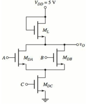
Figure 16.18 Figure for Exercise TYU 16.5
Want to see the full answer?
Check out a sample textbook solution
Chapter 16 Solutions
Microelectronics: Circuit Analysis and Design


- A high-performance microprocessor design requires 200 million logic gates and is placed in apackage that can dissipate 100 W. (a) What is theaverage power that can be dissipated by each logicgate on the chip? (b) If a supply voltage of 1.8 V isused, how much current can be used by each gate?Assume a 33 percent duty cycle. (c) If the averagegate delay for these circuits must be 1 ns, what isthe power-delay product required for the circuits inthis design?arrow_forwardSuppose a ring oscillator is built from N inverters connected in a loop. Each inverter has a minimum delay of tcd and a maximum delay of tcd. If N is odd, determine the range of frequencies at which the oscillator might operate.arrow_forwardDraw the schematic for a four-input NOR gate witha saturated load device. What are the W/L ratios ofall the transistors, based on the reference inverter ? (b) What is VL if all the logic inputs are equal to 1?arrow_forward
- Microprocessors; Draw the figure for flag-bits allocation in an 8086 microprocessor. Explain shortly the meanings of letters used for each flag statues in Assembler.arrow_forwardIf a 3 phase inverter is feeding an appliance that is rated as 207v AC, 60Hz, 100kVA, compute the minimum DC input voltage, that must be feed to the inverter. Assume the Modulation Index Ma to 1. ...arrow_forwardConstruct a bus system using tri state buffer for 2 registers having 4 bits each.arrow_forward
- A high-performance microprocessor design requires 1 billion logic gates and is placed in a package that can dissipate 100 W. (a) What is the average power that can be dissipated by each logic gate onthe chip? (b) If a supply voltage of 1.8 V is used,how much current can be used by each gate? Assume a 25 percent duty cycle. (c) What is the totalcurrent required by the IC chip?arrow_forwardSuppose a ring oscillator is built from N inverters connected in a loop. Each inverter has a minimum delay of tcd and a maximum delay of tpd. If N is odd, determine the range of frequencies at which the oscillator might operate.arrow_forwardAssume Vth = 1V and k = 50mA/V2. Given the schematic below, do the following: 1) Indicate and verify the state of each MOSFET and ?0 for the following input combinations. Fill-out the table below for each assumed state of the MOSFET for every input combination. Use ?ds,on approximation for linear operation. 2) Determine what kind of logic circuit is implemented in the circuit.arrow_forward
- Discuss the evolution of memory technologies, from early magnetic core memory to modern NAND flash and 3D XPoint, and their implications for storage capacity and speed.arrow_forwardDesign transistor level circuits for a 4-bit even parity generator using (i) CCMOS logic (ii) pseudo-nmos logic (iii) pass transistor logic, (iv) transmission gate logic.arrow_forward8086 microprocessor code for assembly language program for given requirement is carry with add two 16 bit bcd numbers.arrow_forward
 Introductory Circuit Analysis (13th Edition)Electrical EngineeringISBN:9780133923605Author:Robert L. BoylestadPublisher:PEARSON
 Delmar's Standard Textbook Of ElectricityElectrical EngineeringISBN:9781337900348Author:Stephen L. HermanPublisher:Cengage Learning
 Programmable Logic ControllersElectrical EngineeringISBN:9780073373843Author:Frank D. PetruzellaPublisher:McGraw-Hill Education
 Fundamentals of Electric CircuitsElectrical EngineeringISBN:9780078028229Author:Charles K Alexander, Matthew SadikuPublisher:McGraw-Hill Education
 Electric Circuits. (11th Edition)Electrical EngineeringISBN:9780134746968Author:James W. Nilsson, Susan RiedelPublisher:PEARSON
 Engineering ElectromagneticsElectrical EngineeringISBN:9780078028151Author:Hayt, William H. (william Hart), Jr, BUCK, John A.Publisher:Mcgraw-hill Education,