
Videos
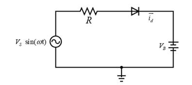
Consider the circuit in Figure 2.4. The input voltage is
a.
The minimum value of the resistance of a battery charger circuit for a given peak battery charging current.
Answer to Problem 2.1TYU
Minimum resistance is
Explanation of Solution
Given Information:
The given values are:
Range of voltage
Calculation:
The battery charger circuit contains a half-wave rectifier as shown below.

Using the Kirchhoff’s Voltage Law, voltage across the resistor is given by,
The current through the resistor,
The peak current through the resistor (or the diode),
The diode current will be maximum when the input voltage is maximum at
From equation (1)
Then, equation (2) can be written as,
Then the minimum value of the resistor,
Substituting the values,
Conclusion:
The minimum resistance value is
b.
The range in peak current and the range in a fraction of cycle diode conducts.
Answer to Problem 2.1TYU
The range in peak current is,
The range in duty cycle is
Explanation of Solution
Given Information:
Calculation:
Here the battery charger circuit contains a halfwave rectifier and the circuit can be drawn as below. The range for the battery voltage is
Using the Kirchhoff’s Voltage Law,
It is known that,
The voltage through the resistor,
Then equation (1) can be written as,
The range for the peak current through the diode,
When the diode is forward biased and at the time diode start conducting, let’s say
Substitute the values
By symmetry, the point where
Then fraction of the time diode is conducting can be calculated as,
Hence,
Conclusion:
The range in peak current is,
The range in the duty cycle is
Want to see more full solutions like this?
Chapter 2 Solutions
Microelectronics: Circuit Analysis and Design
Additional Engineering Textbook Solutions
Principles Of Electric Circuits
Electric machinery fundamentals
Fundamentals of Applied Electromagnetics (7th Edition)
Basic Engineering Circuit Analysis
Engineering Electromagnetics
Electric Circuits (10th Edition)


- Silicon is doped with ND= 2 × 10¹⁵ impurity atoms/cm3 . Assume the electron and hole mobilities for the given impurity are un = 1320 cm2 / V.s, and up=460 cm2 /V.s respectively. Use ni = 1.5 × 10¹⁰/cm3 Calculate the resistivity of silicon. Assume an aluminum line runs diagonally from one corner of a 20 mm × 20 mm silicon material to the other corner. What is the resistance of this line if it is 1 μm thick and 5 μm wide? The resistivity of pure aluminum is 2.82 μΩ-cm.arrow_forwardQ6-Assuming that all of the valence electrons contribute to current flow, (a) calculate the mobility of an electron in copper and (b) calculate the average drift velocity for electrons in a 100 cm copper wire when 10 V are applied. Given( The lattice parameter of copper is 3.6151 10", copper is FCC, a = 5.89 x 10⁵)arrow_forwardGiven a silicon sample of unknown doping. Hall measurement provides the following information: W = 1000 mm, A = 2.5 × 10⁻³cm2, I = 2 10-3 A, magnetic field = 500 Gauss, hall voltage of +150 mV. The majority carriers are: Electrons Holes 1000 150arrow_forward
- A conductor carries a current that maybe regarded as equivalent to the sum of two components, one of them being a continuous direct current of 4.2 amp and the other a superimposed half-wave rectifier current. If the latter has a maximum value of 8.3 amp, calculate the average current in the wire if (a) both components have the same direction, (b) the two components are oppositely directed?arrow_forwardThe expression to calculate the conductivity of extrinsic silicon is given by, The density of acceptor atom is na=1022 m−3na=1022 m-3. The intrinsic density is ni=1.4×10¹⁶ m−3ni=1.4×10¹⁶ m-3. The mobility of electron is μe=0.16 m−3μe=0.16 m-3. The mobility of holes is μh=0.045 m−3μh=0.045 m-3. σ=naμhe 0 / 2 Images Ask an Expert Submit your questionarrow_forwardCalculate the intrinsic carrier density n, for Silicon at I = 292 K. Show all your work and write your answer with 4 significant figures.arrow_forward
- a. SketchtheoutputvoanddeterminethedcleveloftheoutputforthenetworkofFig.2.49. Repeat part (a) if the ideal diode is replaced by a silicon diode. Repeat parts (a) and (b) if Vm is increased to 200 V, and compare solutions using Eqs. (2.7) and (2.8).arrow_forwardA practical silicon-based solar cell is constructed from a n+p junction. a) Explain briefly the meaning of the notation n+? b) Draw a sketch showing the device structure of this solar cell. c) This cell shows a photocurrent IL = 10.9 A under AM1.5G illumination. If the temperature is 25 oC, what is VOC? Assume that the saturated current IS = 1×10⁻⁹ A.arrow_forwardGiven a silicon sample of unknown doping. Hall measurement provides the following information: W = 1000 mm, A = 2.5 × 10⁻³cm2, I = 2 10-3 A, magnetic field = 500 Gauss, hall voltage of +150 mV. The majority carrier concentration is (per cm3)arrow_forward
- The resistance of copper wire with alpha = 0.00393/Co at 20oC is 129 Ω. At 78 oC, its resistance would be about ___.arrow_forwardD2.2. A charge of −0.3μC is located at A(25,−30, 15) (in cm), and asecond charge of 0.5μC is at B(−10, 8, 12) cm. Find E at: (a) the origin;(b) P(15, 20, 50) cm.Ans. 92.3ax − 77.6ay − 94.2az kV/m; 11.9ax − 0.519ay + 12.4az kV/marrow_forwardA copper wire 100 m long must experience avoltage drop of less than 1.5 V when a current of 2.5 A passesthrough it. Given that copper has an electrical conductivity of6.0E7 /(Ὠ-m), compute the minimum diameter of the wire.arrow_forward
 Introductory Circuit Analysis (13th Edition)Electrical EngineeringISBN:9780133923605Author:Robert L. BoylestadPublisher:PEARSON
 Delmar's Standard Textbook Of ElectricityElectrical EngineeringISBN:9781337900348Author:Stephen L. HermanPublisher:Cengage Learning
 Programmable Logic ControllersElectrical EngineeringISBN:9780073373843Author:Frank D. PetruzellaPublisher:McGraw-Hill Education
 Fundamentals of Electric CircuitsElectrical EngineeringISBN:9780078028229Author:Charles K Alexander, Matthew SadikuPublisher:McGraw-Hill Education
 Electric Circuits. (11th Edition)Electrical EngineeringISBN:9780134746968Author:James W. Nilsson, Susan RiedelPublisher:PEARSON
 Engineering ElectromagneticsElectrical EngineeringISBN:9780078028151Author:Hayt, William H. (william Hart), Jr, BUCK, John A.Publisher:Mcgraw-hill Education,