
Microelectronics: Circuit Analysis and Design
4th Edition
ISBN: 9780073380643
Author: Donald A. Neamen
Publisher: McGraw-Hill Companies, The
expand_more
expand_more
format_list_bulleted
Videos
Textbook Question
Chapter 2, Problem 2.31P
Consider the circuit in Figure P2.31. Let
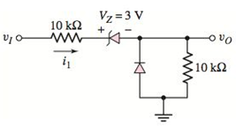
Figure P2.31
Expert Solution & Answer
Want to see the full answer?
Check out a sample textbook solution
Students have asked these similar questions
A conductor carries a current that maybe regarded as equivalent to the sum of two components, one of them being a continuous direct current of 4.2 amp and the other a superimposed half-wave rectifier current. If the latter has a maximum value of 8.3 amp, calculate the average current in the wire if (a) both components have the same direction, (b) the two components are oppositely directed?
2b) A regulator curcuit needs to be designed with an input power supply which has a nominal value of V_PS=20 V and can vary by ± %25 and nominal output voltage of 10 volts. For this purpose a zener diode is employed with specifications given; power rating of 1 W, 10V drop at Iz=25 mA, output load current is to vary between I(subscript L)=0-20 mA and zener resistance of r_Z=5Ω
i) If the minimum Zener current is to be I_Z=5 mA, determine the required R_S
ii) Determine the maximum variation in output voltage
iii) Determine the regulation percent
Consider the circuitshown below, where K = 0.2 mA/V2 and Vto = 0.8V.1) If V1 = 3V, what is the maximum V3 that can be used while M1 remains insaturation?2) Suppose V1 and V3 must be equal. What is the maximum value that theycan have while M1 remains in saturation?
Chapter 2 Solutions
Microelectronics: Circuit Analysis and Design
Ch. 2 - Repeat Example 2.1 if the input voltage is...Ch. 2 - Consider the bridge circuit shown in Figure 2.6(a)...Ch. 2 - Assume the input signal to a rectifier circuit has...Ch. 2 - The input voltage to the halfwave rectifier in...Ch. 2 - Consider the circuit in Figure 2.4. The input...Ch. 2 - The circuit in Figure 2.5(a) is used to rectify a...Ch. 2 - The secondary transformer voltage of the rectifier...Ch. 2 - Determine the fraction (percent) of the cycle that...Ch. 2 - The Zener diode regulator circuit shown in Figure...Ch. 2 - Repeat Example 2.6 for rz=4 . Assume all other...
Ch. 2 - Consider the circuit shown in Figure 2.19. Let...Ch. 2 - Suppose the currentlimiting resistor in Example...Ch. 2 - Suppose the power supply voltage in the circuit...Ch. 2 - Design a parallelbased clipper that will yield the...Ch. 2 - Sketch the steadystate output voltage for the...Ch. 2 - Consider the circuit in Figure 2.23(a). Let R1=5k...Ch. 2 - Determine the steadystate output voltage O for the...Ch. 2 - Design a parallelbased clipper circuit that will...Ch. 2 - Consider the circuit shown in Figure 2.38, in...Ch. 2 - Consider the circuit shown in Figure 2.39. The...Ch. 2 - Repeat Example 2.11 for the case when R1=8k ,...Ch. 2 - The cutin voltage of each diode in the circuit...Ch. 2 - Prob. 2.12TYUCh. 2 - Consider the OR logic circuit shown in Figure...Ch. 2 - Consider the AND logic circuit shown in Figure...Ch. 2 - (a) Photons with an energy of hv=2eV are incident...Ch. 2 - Determine the value of resistance R required to...Ch. 2 - What characteristic of a diode is used in the...Ch. 2 - Prob. 2RQCh. 2 - Describe a simple fullwave diode rectifier circuit...Ch. 2 - Prob. 4RQCh. 2 - Prob. 5RQCh. 2 - Describe a simple Zener diode voltage reference...Ch. 2 - What effect does the Zener diode resistance have...Ch. 2 - What are the general characteristics of diode...Ch. 2 - Describe a simple diode clipper circuit that...Ch. 2 - Prob. 10RQCh. 2 - What one circuit element, besides a diode, is...Ch. 2 - Prob. 12RQCh. 2 - Describe a diode OR logic circuit. Compare a logic...Ch. 2 - Describe a diode AND logic circuit. Compare a...Ch. 2 - Describe a simple circuit that can be used to turn...Ch. 2 - Consider the circuit shown in Figure P2.1. Let...Ch. 2 - For the circuit shown in Figure P2.1, show that...Ch. 2 - A halfwave rectifier such as shown in Figure...Ch. 2 - Consider the battery charging circuit shown in...Ch. 2 - Figure P2.5 shows a simple fullwave battery...Ch. 2 - The fullwave rectifier circuit shown in Figure...Ch. 2 - The input signal voltage to the fullwave rectifier...Ch. 2 - The output resistance of the fullwave rectifier in...Ch. 2 - Repeat Problem 2.8 for the halfwave rectifier in...Ch. 2 - Consider the halfwave rectifier circuit shown in...Ch. 2 - The parameters of the halfwave rectifier circuit...Ch. 2 - The fullwave rectifier circuit shown in Figure...Ch. 2 - Consider the fullwave rectifier circuit in Figure...Ch. 2 - The circuit in Figure P2.14 is a complementary...Ch. 2 - Prob. 2.15PCh. 2 - A fullwave rectifier is to be designed using the...Ch. 2 - Prob. 2.17PCh. 2 - (a) Sketch o versus time for the circuit in Figure...Ch. 2 - Consider the circuit shown in Figure P2.19. The...Ch. 2 - Consider the Zener diode circuit shown in Figure...Ch. 2 - Consider the Zener diode circuit shown in Figure...Ch. 2 - In the voltage regulator circuit in Figure P2.21,...Ch. 2 - A Zener diode is connected in a voltage regulator...Ch. 2 - Consider the Zener diode circuit in Figure 2.19 in...Ch. 2 - Design a voltage regulator circuit such as shown...Ch. 2 - The percent regulation of the Zener diode...Ch. 2 - A voltage regulator is to have a nominal output...Ch. 2 - Consider the circuit in Figure P2.28. Let V=0 ....Ch. 2 - The secondary voltage in the circuit in Figure...Ch. 2 - The parameters in the circuit shown in Figure...Ch. 2 - Consider the circuit in Figure P2.31. Let V=0 (a)...Ch. 2 - Prob. 2.32PCh. 2 - Each diode cutin voltage is 0.7 V for the circuits...Ch. 2 - The diode in the circuit of Figure P2.34(a) has...Ch. 2 - Consider the circuits shown in Figure P2.35. Each...Ch. 2 - Plot O for each circuit in Figure P2.36 for the...Ch. 2 - Consider the parallel clipper circuit in Figure...Ch. 2 - A car’s radio may be subjected to voltage spikes...Ch. 2 - Sketch the steadystate output voltage O versus...Ch. 2 - Prob. D2.40PCh. 2 - Design a diode clamper to generate a steadystate...Ch. 2 - For the circuit in Figure P2.39(b), let V=0 and...Ch. 2 - Repeat Problem 2.42 for the circuit in Figure...Ch. 2 - The diodes in the circuit in Figure P2.44 have...Ch. 2 - In the circuit in Figure P2.45 the diodes have the...Ch. 2 - The diodes in the circuit in Figure P2.46 have the...Ch. 2 - Consider the circuit shown in Figure P2.47. Assume...Ch. 2 - The diode cutin voltage for each diode in the...Ch. 2 - Consider the circuit in Figure P2.49. Each diode...Ch. 2 - Assume V=0.7V for each diode in the circuit in...Ch. 2 - The cutin voltage of each diode in the circuit...Ch. 2 - Let V=0.7V for each diode in the circuit in Figure...Ch. 2 - For the circuit shown in Figure P2.54, let V=0.7V...Ch. 2 - Assume each diode cutin voltage is V=0.7V for the...Ch. 2 - If V=0.7V for the diode in the circuit in Figure...Ch. 2 - Let V=0.7V for the diode in the circuit in Figure...Ch. 2 - Each diode cutin voltage in the circuit in Figure...Ch. 2 - Let V=0.7V for each diode in the circuit shown in...Ch. 2 - Consider the circuit in Figure P2.61. The output...Ch. 2 - Consider the circuit in Figure P2.62. The output...Ch. 2 - Prob. 2.63PCh. 2 - Consider the circuit shown in Figure P2.64. The...Ch. 2 - The lightemitting diode in the circuit shown in...Ch. 2 - The parameters of D1 and D2 in the circuit shown...Ch. 2 - If the resistor in Example 2.12 is R=2 and the...Ch. 2 - Consider the photodiode circuit shown in Figure...Ch. 2 - Consider the fullwave bridge rectifier circuit....Ch. 2 - Design a simple dc voltage source using a...Ch. 2 - A clipper is to be designed such that O=2.5V for...Ch. 2 - Design a circuit to provide the voltage transfer...
Knowledge Booster


Learn more about
Need a deep-dive on the concept behind this application? Look no further. Learn more about this topic, electrical-engineering and related others by exploring similar questions and additional content below.Similar questions
- Problem 1. We have identical crystalline silicon solar cells available, with a short circuit current of 4 A and an open circuitvoltage of 0.6 V at STC. These cells are used to make a PV module with 54 cells connected in series. I. What is the open circuit voltage of the module at STC? Assume that the interconnection losses arenegligible.II. What is the short circuit current of the module at STC? III. Assume that the module does not have any bypass diodes. If the module is partially shaded and one ofthe cells is only able to produce 2 A, what will be the new short circuit current under these conditions?arrow_forwardDEVELOP AND JUSTIFY YOUR RESPONSE. Determine the total current when BT1 = 15.9 V, BT2 = 7.5 V, the Resistance R1 = 1.1 kΩ and the Resistance R2 = 4.4 kΩ, Consider voltage drop of the diodes of Si = 0.7V A. -2.55 mA. B. 1,40 mA. C. 4.25 mA. D. -1.53 mA.arrow_forwardA practical silicon-based solar cell is constructed from a n+p junction. a) Explain briefly the meaning of the notation n+? b) Draw a sketch showing the device structure of this solar cell. c) This cell shows a photocurrent IL = 10.9 A under AM1.5G illumination. If the temperature is 25 oC, what is VOC? Assume that the saturated current IS = 1×10⁻⁹ A.arrow_forward
- In the given system; Va, Vb, Vc effective value is 220V, Ly=300 mH and Ry=22 Ohms.It was observed that the yuk current is continuous when the tristorier is triggered for alpha=65 degrees; and D1the average value of the diode current was calculated as ID1 avg = 1.703A.Accordingly, calculate the average value of the current flowing through T3. IT3_ avg=?arrow_forwardDesign rectifier circuits to provide an output of100 VDC using a.) HWR b.) Center-tappedFWR and c.) Bridge-Type FWR circuits. For each circuit, calculate the transformer peakvoltage rating, the diode PIV ratings, and thetransformer turns ratio, if power is taken fromthe 220V line ac supplyarrow_forwardWhat is the operation of the circuit below? Describe qualitativelyarrow_forward
- Q3: For the circuit shown in Figure 2, find the following:1. Describe the function of the circuit in terms of simple of semiconductor behavior.2. Evaluate the output voltage vo, assuming vs is 10 Sine (200t) mV, RE1 =100 Ω,and RE2 =900 Ω. The bypass capacitor (CE) is in parallel with RE2. 3. explain the characteristics of the amplifier.arrow_forwardSuppose that NA(x) = No exp(−x/L) in a region of silicon extending from x =0 to x = 8μm,where No is a constant. Assume that p(x) = NA(x). Assuming that jp must be zero in thermale quilibrium, show that a built-in electric field must exist and find its value for L =1 μm and No =1018/cm3.arrow_forwardConsider the circuitshown below, where K = 0.2 mA/V2 and Vto = 0.8V.Suppose V1 and V3 must be equal. What is the maximum value that theycan have while M1 remains in saturation?arrow_forward
- Apply each of diodeapproximations and determine:a. Current through D1b. Voltage across D2c. Voltage across R3 GIVEN: R1 = 2 kΩ, R2 = 1.2 kΩ, R3 = 6.8 kΩ E= 10 V D1: Si, rB = 2 Ω, rR = 220 kΩ D2: Si, rB = 5 Ω, rR = 560 kΩ DETERMING FIRST IF IT IS A FORWARD BIASED OR REVERSED BIASED THEN, SOLVE IN FIRST APPROXIMATION, SECOND APPROXIMATION AND THIRD APPROXIMATION SHOW THE CIRCUIT DIAGRAM IN EACH APPROXIMATIONarrow_forwardQ2: For the single phase full wave semi controlled rectifier shown: 1-Draw the v-i waveforms for the circuit vm 2-Prove that: lav =~ (1+cos @) 3-Maximum voltage across the load if the AC supply voltage is 208V .arrow_forwardFive years ago, when the relevant cost index was 120, a nuclear centrifuge cost $40,000. The centrifuge had a capacity of separating 1500 gallons of ionized solution per hour. Today, the boss wants to build a centrifuge with capacity of 4500 gallons per hour, but the cost index now is 300. Assuming a power-sizing exponent of 0.75, determine the approximate cost in today's dollars of the new, larger reactorarrow_forward
arrow_back_ios
SEE MORE QUESTIONS
arrow_forward_ios
Recommended textbooks for you
 Introductory Circuit Analysis (13th Edition)Electrical EngineeringISBN:9780133923605Author:Robert L. BoylestadPublisher:PEARSON
 Delmar's Standard Textbook Of ElectricityElectrical EngineeringISBN:9781337900348Author:Stephen L. HermanPublisher:Cengage Learning
 Programmable Logic ControllersElectrical EngineeringISBN:9780073373843Author:Frank D. PetruzellaPublisher:McGraw-Hill Education
 Fundamentals of Electric CircuitsElectrical EngineeringISBN:9780078028229Author:Charles K Alexander, Matthew SadikuPublisher:McGraw-Hill Education
 Electric Circuits. (11th Edition)Electrical EngineeringISBN:9780134746968Author:James W. Nilsson, Susan RiedelPublisher:PEARSON
 Engineering ElectromagneticsElectrical EngineeringISBN:9780078028151Author:Hayt, William H. (william Hart), Jr, BUCK, John A.Publisher:Mcgraw-hill Education,
Introductory Circuit Analysis (13th Edition)
Electrical Engineering
ISBN:9780133923605
Author:Robert L. Boylestad
Publisher:PEARSON
Delmar's Standard Textbook Of Electricity
Electrical Engineering
ISBN:9781337900348
Author:Stephen L. Herman
Publisher:Cengage Learning
Programmable Logic Controllers
Electrical Engineering
ISBN:9780073373843
Author:Frank D. Petruzella
Publisher:McGraw-Hill Education
Fundamentals of Electric Circuits
Electrical Engineering
ISBN:9780078028229
Author:Charles K Alexander, Matthew Sadiku
Publisher:McGraw-Hill Education
Electric Circuits. (11th Edition)
Electrical Engineering
ISBN:9780134746968
Author:James W. Nilsson, Susan Riedel
Publisher:PEARSON
Engineering Electromagnetics
Electrical Engineering
ISBN:9780078028151
Author:Hayt, William H. (william Hart), Jr, BUCK, John A.
Publisher:Mcgraw-hill Education,
Three-Phase Half-Wave Rectifier Operation; Author: katkimshow;https://www.youtube.com/watch?v=Uhbr6tbMB9A;License: Standard Youtube License