
Concept explainers
Videos
Consider the circuit in Figure P2.49. Each diode cut−in voltage is
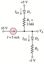
Figure P2.49
Want to see the full answer?
Check out a sample textbook solution
Chapter 2 Solutions
Microelectronics: Circuit Analysis and Design


- 2b) A regulator curcuit needs to be designed with an input power supply which has a nominal value of V_PS=20 V and can vary by ± %25 and nominal output voltage of 10 volts. For this purpose a zener diode is employed with specifications given; power rating of 1 W, 10V drop at Iz=25 mA, output load current is to vary between I(subscript L)=0-20 mA and zener resistance of r_Z=5Ω i) If the minimum Zener current is to be I_Z=5 mA, determine the required R_S ii) Determine the maximum variation in output voltage iii) Determine the regulation percentarrow_forwardFor the half-wave rectifier circuit shown, the diode is not ideal and is modeled as an ideal voltage source of value Vf= =0.65V in series with an ideal diode. Vin= 2sin(2π10t) and R= 470Ω. What is the magnitude of the diode current at time t=60mst=60ms? 2- At what time between 0and T/4 seconds is the magnitude of the diode current equal to 2.66mA? Tis the period of Vin Enter your answer in millisecondsarrow_forwardA drift current density of 120A/cm2 is established in n-type silicon with an applied electric field of 18V/cm. If the electron and hole mobilities are µn =1250 cm2/V-s and µp =450 cm2/V-s, respectively, determine the required doping concentration. 2.5M 2. The circuit in figurearrow_forward
- 2.13 Two diodes are connected in series as shown in Figure 2.11a to share a total de reverse volt age of VD=5 KV. The reverse leakage currents of two diode I=25 mA, 1,2 = 30 mA. (a) Find the diode voltage if the voltage sharing resistances R₁ and R₂ are equal R₁ = R₂ = 200 KN. (b) Find the voltage sharing resistance R₁ and R₂ if the diode voltage are equal Vd1= Vd2= Vd/2arrow_forwardDiodesFill in the blanks with the words belowcheck valve, conductance, convert, crystalline, impurities, infinite, galena, p–n junction, rectifying,resistance, selenium, semiconductor, switching circuits, tailored, temperature, threshold, two-terminal,unidirectionalA diode is a 1 ………………… electronic component that conducts current primarily in one direction(asymmetric 2 ………………..); it has low (ideally zero) 3 ……………… in one direction, and high (ideally4 ………………..) resistance in the other. A 5 ………….. diode, the most common type today, is a 6……….. piece of semiconductor material with a 7 ………………. connected to two electrical terminals. Avacuum tube diode has two electrodes, a plate (anode) and a heated cathode. Semiconductor diodes were thefirst semiconductor electronic devices. The discovery of crystals' 8 ……………… abilities was made byGerman physicist Ferdinand Braun in 1874. The first semiconductor diodes, developed around 1906, weremade of mineral crystals such as 9 ……………….. . Today,…arrow_forwardFill in the blanks with the words belowcheck valve, conductance, convert, crystalline, impurities, infinite, galena, p–n junction, rectifying,resistance, selenium, semiconductor, switching circuits, tailored, temperature, threshold, two-terminal,unidirectionalA diode is a 1 ………………… electronic component that conducts current primarily in one direction(asymmetric 2 ………………..); it has low (ideally zero) 3 ……………… in one direction, and high (ideally4 ………………..) resistance in the other. A 5 ………….. diode, the most common type today, is a 6……….. piece of semiconductor material with a 7 ………………. connected to two electrical terminals. Avacuum tube diode has two electrodes, a plate (anode) and a heated cathode. Semiconductor diodes were thefirst semiconductor electronic devices. The discovery of crystals' 8 ……………… abilities was made byGerman physicist Ferdinand Braun in 1874. The first semiconductor diodes, developed around 1906, weremade of mineral crystals such as 9 ……………….. . Today, most…arrow_forward
- DEVELOP AND JUSTIFY YOUR RESPONSE. Determine the total current when BT1 = 15.9 V, BT2 = 7.5 V, the Resistance R1 = 1.1 kΩ and the Resistance R2 = 4.4 kΩ, Consider voltage drop of the diodes of Si = 0.7V A. -2.55 mA. B. 1,40 mA. C. 4.25 mA. D. -1.53 mA.arrow_forwardDiodes D1, D2, D3 and D4 are identical Silicon diodes with forward voltage drop of 0.7volts. Consider vi to be the circuit's input voltage.A) Under what input conditions will diode D1 conduct? B) If D1 is conducting, express vo in terms of vi. C) Under what conditions will diode D4 conduct? D) If D4 is conducting, express vo in terms of vi. E) Under what input conditions will none of the diodes be conducting? F) If none of the diodes are conducting, what is vo? G) The input to the circuit has the waveform shown below. Plot the waveform of thevoltage vo. Show all the important quantities in your plot.arrow_forwardWhile constructing a Bridge rectifier, the designer mistakenly has swapped the terminals of D3 as shown in the figure below, where • Diode D3 is damaged so that it is always open circuit regardless of the applied voltage. • vs(t) is a sinusoidal signal with a peak value (Vs = 5 V). • Diodes are modelled using the constant voltage model with VDO = 0.7 V • The ac line voltage has an rms value of 120 V and a frequency (f) = 60 Hz • The resistance RL = 10 kohm. a) Calculate the transformer turns ratio (N1/N2) if vs(t) is obtained from the secondary side of the transformer whose primary side is connected to the ac line voltage (which has a 120 V rms value). b) Plot in the same graph the input signal vs(t) and the output signal vout(t) (show all details including amplitudes, time instances, etc.) c) Calculate the rms values of the output signal vout(t). (hint: sin2 (x) = 0.5(1- cos(2x))) d) If a capacitor C = 3.58 µF is connected across R = 10 kohm, repeat (b) in a new graph e) With the…arrow_forward
- While constructing a Bridge rectifier, the designer mistakenly has swapped the terminals of D3 as shown in the figure below, where • Diode D3 is damaged so that it is always open circuit regardless of the applied voltage. • vs(t) is a sinusoidal signal with a peak value (Vs = 5 V). • Diodes are modelled using the constant voltage model with VDO = 0.7 V • The ac line voltage has an rms value of 120 V and a frequency (f) = 60 Hz • The resistance RL = 10 kohm. a) Calculate the transformer turns ratio (N1/N2) if vs(t) is obtained from the secondary side of the transformer whose primary side is connected to the ac line voltage (which has a 120 V rms value). b) Plot in the same graph the input signal vs(t) and the output signal vout(t) (show all details including amplitudes, time instances, etc.) Please plot the graph. c) Calculate the rms values of the output signal vout(t). (hint: sin2 (x) = 0.5(1- cos(2x))) d) If a capacitor C = 3.58 µF is connected across R = 10 kohm, repeat (b) in a new…arrow_forward(a) Calculate the current at t = 0+ in the circuit as shwon if R1 is changed to 5 Ω. (b) Calculate IF, IR, and the storage time expected when the diode is switched off at t =10 μs if τT =250 ns.arrow_forwardQ2 (b) Multiple diodes circuit is given in Figure (i) Identify the condition for Si and Ge diodes. (ii) Determine the current flowing into Si and Ge diodes. (iii) Calculate the output voltage, Voarrow_forward
 Introductory Circuit Analysis (13th Edition)Electrical EngineeringISBN:9780133923605Author:Robert L. BoylestadPublisher:PEARSON
 Delmar's Standard Textbook Of ElectricityElectrical EngineeringISBN:9781337900348Author:Stephen L. HermanPublisher:Cengage Learning
 Programmable Logic ControllersElectrical EngineeringISBN:9780073373843Author:Frank D. PetruzellaPublisher:McGraw-Hill Education
 Fundamentals of Electric CircuitsElectrical EngineeringISBN:9780078028229Author:Charles K Alexander, Matthew SadikuPublisher:McGraw-Hill Education
 Electric Circuits. (11th Edition)Electrical EngineeringISBN:9780134746968Author:James W. Nilsson, Susan RiedelPublisher:PEARSON
 Engineering ElectromagneticsElectrical EngineeringISBN:9780078028151Author:Hayt, William H. (william Hart), Jr, BUCK, John A.Publisher:Mcgraw-hill Education,