
Microelectronics: Circuit Analysis and Design
4th Edition
ISBN: 9780073380643
Author: Donald A. Neamen
Publisher: McGraw-Hill Companies, The
expand_more
expand_more
format_list_bulleted
Concept explainers
Videos
Textbook Question
Chapter 2, Problem 2.18P
(a) Sketch
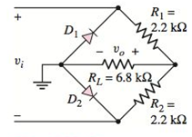
Figure P2.18
Expert Solution & Answer
Want to see the full answer?
Check out a sample textbook solution
Students have asked these similar questions
In the figure given we have u(t)=10· coswt [V]. We assume the diodesand the A-meter (A) to be ideal.a) Plot the waveform of the current flowing through the A-m in scale.b) What is the reading of the A-m, if it is moving-coil type?c) What is the reading of the A-m, if it is moving-iron type?d) Calculate the power factor of the WHOLE structure.
A pure element is connected across an AC signal. CH1 and CH2 measures the voltage and current respectively:
CH1 (Yellow) Settings:
CH2 (Blue) Settings:
Volts/Div: 50V
Current Probe Ratio: 100 mV/mA
Time/Div: 5ms
Volts/Div: 20V
Probe Settings: X1
Time/Div: 5ms
Probe Settings: X1
If ?? (distance between two ‘purple’ cursors) is 5ms, determine:a. CH2 Peak Currentb. CH2 RMS Currentc. Impedance of the pure elementd. Type of load. If reactive, indicate the values of inductance or capacitance
Consider the circuit shown in figure 2-8. the circuit operates at 60 hz, the rms of the voltage is 120 volts, the resistor has a value of 40 ohm, the inductor is 0.1592 H, and the capacitance is 33.16 UF. a) Find the impedance of the inductor and the capacitor. b) Find the current in each leg of the circuit and the total current from the source. c) Draw a phasor diagram showing the source voltage and all the currents. d) Find the total impedance of the RLC parallel combination
Chapter 2 Solutions
Microelectronics: Circuit Analysis and Design
Ch. 2 - Repeat Example 2.1 if the input voltage is...Ch. 2 - Consider the bridge circuit shown in Figure 2.6(a)...Ch. 2 - Assume the input signal to a rectifier circuit has...Ch. 2 - The input voltage to the halfwave rectifier in...Ch. 2 - Consider the circuit in Figure 2.4. The input...Ch. 2 - The circuit in Figure 2.5(a) is used to rectify a...Ch. 2 - The secondary transformer voltage of the rectifier...Ch. 2 - Determine the fraction (percent) of the cycle that...Ch. 2 - The Zener diode regulator circuit shown in Figure...Ch. 2 - Repeat Example 2.6 for rz=4 . Assume all other...
Ch. 2 - Consider the circuit shown in Figure 2.19. Let...Ch. 2 - Suppose the currentlimiting resistor in Example...Ch. 2 - Suppose the power supply voltage in the circuit...Ch. 2 - Design a parallelbased clipper that will yield the...Ch. 2 - Sketch the steadystate output voltage for the...Ch. 2 - Consider the circuit in Figure 2.23(a). Let R1=5k...Ch. 2 - Determine the steadystate output voltage O for the...Ch. 2 - Design a parallelbased clipper circuit that will...Ch. 2 - Consider the circuit shown in Figure 2.38, in...Ch. 2 - Consider the circuit shown in Figure 2.39. The...Ch. 2 - Repeat Example 2.11 for the case when R1=8k ,...Ch. 2 - The cutin voltage of each diode in the circuit...Ch. 2 - Prob. 2.12TYUCh. 2 - Consider the OR logic circuit shown in Figure...Ch. 2 - Consider the AND logic circuit shown in Figure...Ch. 2 - (a) Photons with an energy of hv=2eV are incident...Ch. 2 - Determine the value of resistance R required to...Ch. 2 - What characteristic of a diode is used in the...Ch. 2 - Prob. 2RQCh. 2 - Describe a simple fullwave diode rectifier circuit...Ch. 2 - Prob. 4RQCh. 2 - Prob. 5RQCh. 2 - Describe a simple Zener diode voltage reference...Ch. 2 - What effect does the Zener diode resistance have...Ch. 2 - What are the general characteristics of diode...Ch. 2 - Describe a simple diode clipper circuit that...Ch. 2 - Prob. 10RQCh. 2 - What one circuit element, besides a diode, is...Ch. 2 - Prob. 12RQCh. 2 - Describe a diode OR logic circuit. Compare a logic...Ch. 2 - Describe a diode AND logic circuit. Compare a...Ch. 2 - Describe a simple circuit that can be used to turn...Ch. 2 - Consider the circuit shown in Figure P2.1. Let...Ch. 2 - For the circuit shown in Figure P2.1, show that...Ch. 2 - A halfwave rectifier such as shown in Figure...Ch. 2 - Consider the battery charging circuit shown in...Ch. 2 - Figure P2.5 shows a simple fullwave battery...Ch. 2 - The fullwave rectifier circuit shown in Figure...Ch. 2 - The input signal voltage to the fullwave rectifier...Ch. 2 - The output resistance of the fullwave rectifier in...Ch. 2 - Repeat Problem 2.8 for the halfwave rectifier in...Ch. 2 - Consider the halfwave rectifier circuit shown in...Ch. 2 - The parameters of the halfwave rectifier circuit...Ch. 2 - The fullwave rectifier circuit shown in Figure...Ch. 2 - Consider the fullwave rectifier circuit in Figure...Ch. 2 - The circuit in Figure P2.14 is a complementary...Ch. 2 - Prob. 2.15PCh. 2 - A fullwave rectifier is to be designed using the...Ch. 2 - Prob. 2.17PCh. 2 - (a) Sketch o versus time for the circuit in Figure...Ch. 2 - Consider the circuit shown in Figure P2.19. The...Ch. 2 - Consider the Zener diode circuit shown in Figure...Ch. 2 - Consider the Zener diode circuit shown in Figure...Ch. 2 - In the voltage regulator circuit in Figure P2.21,...Ch. 2 - A Zener diode is connected in a voltage regulator...Ch. 2 - Consider the Zener diode circuit in Figure 2.19 in...Ch. 2 - Design a voltage regulator circuit such as shown...Ch. 2 - The percent regulation of the Zener diode...Ch. 2 - A voltage regulator is to have a nominal output...Ch. 2 - Consider the circuit in Figure P2.28. Let V=0 ....Ch. 2 - The secondary voltage in the circuit in Figure...Ch. 2 - The parameters in the circuit shown in Figure...Ch. 2 - Consider the circuit in Figure P2.31. Let V=0 (a)...Ch. 2 - Prob. 2.32PCh. 2 - Each diode cutin voltage is 0.7 V for the circuits...Ch. 2 - The diode in the circuit of Figure P2.34(a) has...Ch. 2 - Consider the circuits shown in Figure P2.35. Each...Ch. 2 - Plot O for each circuit in Figure P2.36 for the...Ch. 2 - Consider the parallel clipper circuit in Figure...Ch. 2 - A car’s radio may be subjected to voltage spikes...Ch. 2 - Sketch the steadystate output voltage O versus...Ch. 2 - Prob. D2.40PCh. 2 - Design a diode clamper to generate a steadystate...Ch. 2 - For the circuit in Figure P2.39(b), let V=0 and...Ch. 2 - Repeat Problem 2.42 for the circuit in Figure...Ch. 2 - The diodes in the circuit in Figure P2.44 have...Ch. 2 - In the circuit in Figure P2.45 the diodes have the...Ch. 2 - The diodes in the circuit in Figure P2.46 have the...Ch. 2 - Consider the circuit shown in Figure P2.47. Assume...Ch. 2 - The diode cutin voltage for each diode in the...Ch. 2 - Consider the circuit in Figure P2.49. Each diode...Ch. 2 - Assume V=0.7V for each diode in the circuit in...Ch. 2 - The cutin voltage of each diode in the circuit...Ch. 2 - Let V=0.7V for each diode in the circuit in Figure...Ch. 2 - For the circuit shown in Figure P2.54, let V=0.7V...Ch. 2 - Assume each diode cutin voltage is V=0.7V for the...Ch. 2 - If V=0.7V for the diode in the circuit in Figure...Ch. 2 - Let V=0.7V for the diode in the circuit in Figure...Ch. 2 - Each diode cutin voltage in the circuit in Figure...Ch. 2 - Let V=0.7V for each diode in the circuit shown in...Ch. 2 - Consider the circuit in Figure P2.61. The output...Ch. 2 - Consider the circuit in Figure P2.62. The output...Ch. 2 - Prob. 2.63PCh. 2 - Consider the circuit shown in Figure P2.64. The...Ch. 2 - The lightemitting diode in the circuit shown in...Ch. 2 - The parameters of D1 and D2 in the circuit shown...Ch. 2 - If the resistor in Example 2.12 is R=2 and the...Ch. 2 - Consider the photodiode circuit shown in Figure...Ch. 2 - Consider the fullwave bridge rectifier circuit....Ch. 2 - Design a simple dc voltage source using a...Ch. 2 - A clipper is to be designed such that O=2.5V for...Ch. 2 - Design a circuit to provide the voltage transfer...
Knowledge Booster


Learn more about
Need a deep-dive on the concept behind this application? Look no further. Learn more about this topic, electrical-engineering and related others by exploring similar questions and additional content below.Similar questions
- A conductor carries a current that may be regarded as equivalent to the sum of two components, one of them being a continuous direct current of 4.2 amp and the other a superimposed full-wave rectifier current. If the latter has a maximum value of 6.4 amp, calculate the average current in the wire if (a) both components have the same direction, (b) the two components are oppositely directed?arrow_forwardDiscuss Potential barriers of combined heat and power (CHP).arrow_forward(i) A fully-controlled single-phase bridge rectifier is supplied from a 50Hz, 220/120 V transformer .The rectifier supplying a highly inductive load of 10 Ohm resistor. For a firing angle of 45º, determine the rectified voltage, the rectified current and the power factor. (ii) If the current extinction angle β =200˚; Determine whether the current is continuous or discontinuous (iii) Sketch the appropriate load voltage and load current waveformarrow_forward
- 13. At what amperage differences will a GFCI trip? 14. What do DC and AC stand for? 15. True or False: An electron holds a positive chargearrow_forwardQ ) For the full- wave uncontrolled rectifier circuit supplying a series resistive Thesupply voltage is v =300 sinωt , the supply frequency is 50 Hz and the loadparameter values are: R =05 Ω,a) Sketch the diagram of electrical circuitb) Sketch the load voltage and current waveforms .c) Calculate the load currentd) Calculate the average DC load voltage Vdc .e) Calculate the supply power to the loaarrow_forwardexplain in a summarized form the procedures for the calculation of elements for the construction of a PROTOTYPE OF PIEZOELECTRIC TILE FOR THE GENERATION OF ELECTRIC ENERGY THROUGH THE PEDESTRIAN TRAFFICarrow_forward
- a. What are the magnitude and direction of the current in the20 Ω resistor in Figure P23.8?b. Draw a graph of the potential as a function of the distance traveled through the circuit, traveling clockwise from the lower left corner, where V = 0 V. See Figure P23.9 for an example of such a graph.arrow_forwardA mild street ring having across sectional area of 600 sq mm and a mean circumference of 500 mm has a coil of 300 turns uniformly around it. Calculate the reactance at the ring and the current required to produce a flux of 800 uwb in the ring. If the relative permeability is 400.arrow_forwardQuestion : Explain the concepts of lattice matched hetero-structure. Don’t copy other works. Sub:Optoelectronic Dept: EEEarrow_forward
- Discuss briefly the importance of renewable energy.arrow_forwardA conductor carries a current that maybe regarded as equivalent to the sum of two components, one of them being a continuous direct current of 4.2 amp and the other a superimposed half-wave rectifier current. If the latter has a maximum value of 8.3 amp, calculate the average current in the wire if (a) both components have the same direction, (b) the two components are oppositely directed?arrow_forwardExplain the modifciation to be made to the schering bridge for the following situations: i) Hihg dissipation factor test objects II) High capacitance test objects Explain in easy language so i can understandarrow_forward
arrow_back_ios
SEE MORE QUESTIONS
arrow_forward_ios
Recommended textbooks for you
 EBK ELECTRICAL WIRING RESIDENTIALElectrical EngineeringISBN:9781337516549Author:SimmonsPublisher:CENGAGE LEARNING - CONSIGNMENT
EBK ELECTRICAL WIRING RESIDENTIAL
Electrical Engineering
ISBN:9781337516549
Author:Simmons
Publisher:CENGAGE LEARNING - CONSIGNMENT
Types of Energy for Kids - Renewable and Non-Renewable Energies; Author: Smile and Learn - English;https://www.youtube.com/watch?v=w16-Uems2Qo;License: Standard Youtube License