
Microelectronics: Circuit Analysis and Design
4th Edition
ISBN: 9780073380643
Author: Donald A. Neamen
Publisher: McGraw-Hill Companies, The
expand_more
expand_more
format_list_bulleted
Concept explainers
Videos
Textbook Question
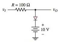
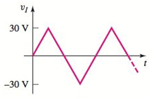
Chapter 2, Problem 2.34P
The diode in the circuit of Figure P2.34(a) has piecewise linear parameters
Expert Solution & Answer
Want to see the full answer?
Check out a sample textbook solution
Students have asked these similar questions
For the half-wave rectifier circuit shown, the diode is not ideal and
is modeled as an ideal voltage source of value Vf= =0.65V in series
with an ideal diode. Vin= 2sin(2π10t) and R= 470Ω.
What is the magnitude of the diode current at time t=60mst=60ms?
2- At what time between 0and T/4 seconds is the magnitude of the diode current equal to 2.66mA? Tis the period of Vin Enter your answer in milliseconds
Q2
(b) Multiple diodes circuit is given in Figure
(i) Identify the condition for Si and Ge diodes.
(ii) Determine the current flowing into Si and Ge diodes.
(iii) Calculate the output voltage, Vo
accepting that D1 and D2 diodes have the same properties in the circuit given in the figurea) output voltage, b) current flowing through the resistor,c) current flowing from diodes calculate.
Chapter 2 Solutions
Microelectronics: Circuit Analysis and Design
Ch. 2 - Repeat Example 2.1 if the input voltage is...Ch. 2 - Consider the bridge circuit shown in Figure 2.6(a)...Ch. 2 - Assume the input signal to a rectifier circuit has...Ch. 2 - The input voltage to the halfwave rectifier in...Ch. 2 - Consider the circuit in Figure 2.4. The input...Ch. 2 - The circuit in Figure 2.5(a) is used to rectify a...Ch. 2 - The secondary transformer voltage of the rectifier...Ch. 2 - Determine the fraction (percent) of the cycle that...Ch. 2 - The Zener diode regulator circuit shown in Figure...Ch. 2 - Repeat Example 2.6 for rz=4 . Assume all other...
Ch. 2 - Consider the circuit shown in Figure 2.19. Let...Ch. 2 - Suppose the currentlimiting resistor in Example...Ch. 2 - Suppose the power supply voltage in the circuit...Ch. 2 - Design a parallelbased clipper that will yield the...Ch. 2 - Sketch the steadystate output voltage for the...Ch. 2 - Consider the circuit in Figure 2.23(a). Let R1=5k...Ch. 2 - Determine the steadystate output voltage O for the...Ch. 2 - Design a parallelbased clipper circuit that will...Ch. 2 - Consider the circuit shown in Figure 2.38, in...Ch. 2 - Consider the circuit shown in Figure 2.39. The...Ch. 2 - Repeat Example 2.11 for the case when R1=8k ,...Ch. 2 - The cutin voltage of each diode in the circuit...Ch. 2 - Prob. 2.12TYUCh. 2 - Consider the OR logic circuit shown in Figure...Ch. 2 - Consider the AND logic circuit shown in Figure...Ch. 2 - (a) Photons with an energy of hv=2eV are incident...Ch. 2 - Determine the value of resistance R required to...Ch. 2 - What characteristic of a diode is used in the...Ch. 2 - Prob. 2RQCh. 2 - Describe a simple fullwave diode rectifier circuit...Ch. 2 - Prob. 4RQCh. 2 - Prob. 5RQCh. 2 - Describe a simple Zener diode voltage reference...Ch. 2 - What effect does the Zener diode resistance have...Ch. 2 - What are the general characteristics of diode...Ch. 2 - Describe a simple diode clipper circuit that...Ch. 2 - Prob. 10RQCh. 2 - What one circuit element, besides a diode, is...Ch. 2 - Prob. 12RQCh. 2 - Describe a diode OR logic circuit. Compare a logic...Ch. 2 - Describe a diode AND logic circuit. Compare a...Ch. 2 - Describe a simple circuit that can be used to turn...Ch. 2 - Consider the circuit shown in Figure P2.1. Let...Ch. 2 - For the circuit shown in Figure P2.1, show that...Ch. 2 - A halfwave rectifier such as shown in Figure...Ch. 2 - Consider the battery charging circuit shown in...Ch. 2 - Figure P2.5 shows a simple fullwave battery...Ch. 2 - The fullwave rectifier circuit shown in Figure...Ch. 2 - The input signal voltage to the fullwave rectifier...Ch. 2 - The output resistance of the fullwave rectifier in...Ch. 2 - Repeat Problem 2.8 for the halfwave rectifier in...Ch. 2 - Consider the halfwave rectifier circuit shown in...Ch. 2 - The parameters of the halfwave rectifier circuit...Ch. 2 - The fullwave rectifier circuit shown in Figure...Ch. 2 - Consider the fullwave rectifier circuit in Figure...Ch. 2 - The circuit in Figure P2.14 is a complementary...Ch. 2 - Prob. 2.15PCh. 2 - A fullwave rectifier is to be designed using the...Ch. 2 - Prob. 2.17PCh. 2 - (a) Sketch o versus time for the circuit in Figure...Ch. 2 - Consider the circuit shown in Figure P2.19. The...Ch. 2 - Consider the Zener diode circuit shown in Figure...Ch. 2 - Consider the Zener diode circuit shown in Figure...Ch. 2 - In the voltage regulator circuit in Figure P2.21,...Ch. 2 - A Zener diode is connected in a voltage regulator...Ch. 2 - Consider the Zener diode circuit in Figure 2.19 in...Ch. 2 - Design a voltage regulator circuit such as shown...Ch. 2 - The percent regulation of the Zener diode...Ch. 2 - A voltage regulator is to have a nominal output...Ch. 2 - Consider the circuit in Figure P2.28. Let V=0 ....Ch. 2 - The secondary voltage in the circuit in Figure...Ch. 2 - The parameters in the circuit shown in Figure...Ch. 2 - Consider the circuit in Figure P2.31. Let V=0 (a)...Ch. 2 - Prob. 2.32PCh. 2 - Each diode cutin voltage is 0.7 V for the circuits...Ch. 2 - The diode in the circuit of Figure P2.34(a) has...Ch. 2 - Consider the circuits shown in Figure P2.35. Each...Ch. 2 - Plot O for each circuit in Figure P2.36 for the...Ch. 2 - Consider the parallel clipper circuit in Figure...Ch. 2 - A car’s radio may be subjected to voltage spikes...Ch. 2 - Sketch the steadystate output voltage O versus...Ch. 2 - Prob. D2.40PCh. 2 - Design a diode clamper to generate a steadystate...Ch. 2 - For the circuit in Figure P2.39(b), let V=0 and...Ch. 2 - Repeat Problem 2.42 for the circuit in Figure...Ch. 2 - The diodes in the circuit in Figure P2.44 have...Ch. 2 - In the circuit in Figure P2.45 the diodes have the...Ch. 2 - The diodes in the circuit in Figure P2.46 have the...Ch. 2 - Consider the circuit shown in Figure P2.47. Assume...Ch. 2 - The diode cutin voltage for each diode in the...Ch. 2 - Consider the circuit in Figure P2.49. Each diode...Ch. 2 - Assume V=0.7V for each diode in the circuit in...Ch. 2 - The cutin voltage of each diode in the circuit...Ch. 2 - Let V=0.7V for each diode in the circuit in Figure...Ch. 2 - For the circuit shown in Figure P2.54, let V=0.7V...Ch. 2 - Assume each diode cutin voltage is V=0.7V for the...Ch. 2 - If V=0.7V for the diode in the circuit in Figure...Ch. 2 - Let V=0.7V for the diode in the circuit in Figure...Ch. 2 - Each diode cutin voltage in the circuit in Figure...Ch. 2 - Let V=0.7V for each diode in the circuit shown in...Ch. 2 - Consider the circuit in Figure P2.61. The output...Ch. 2 - Consider the circuit in Figure P2.62. The output...Ch. 2 - Prob. 2.63PCh. 2 - Consider the circuit shown in Figure P2.64. The...Ch. 2 - The lightemitting diode in the circuit shown in...Ch. 2 - The parameters of D1 and D2 in the circuit shown...Ch. 2 - If the resistor in Example 2.12 is R=2 and the...Ch. 2 - Consider the photodiode circuit shown in Figure...Ch. 2 - Consider the fullwave bridge rectifier circuit....Ch. 2 - Design a simple dc voltage source using a...Ch. 2 - A clipper is to be designed such that O=2.5V for...Ch. 2 - Design a circuit to provide the voltage transfer...
Knowledge Booster


Learn more about
Need a deep-dive on the concept behind this application? Look no further. Learn more about this topic, electrical-engineering and related others by exploring similar questions and additional content below.Similar questions
- Consider the full-wave rectifier circuit shown below, where• vS(t) is a sinusoidal signal with a peak value (Vs = 5 V).• Diodes are modelled using constant voltage model with VDO = 0.7 V• The ac line voltage has an rms value of 120 V and a frequency (f) = 60 Hza) Calculate the transformer turns ratio. b) Plot in the same graph signal vS(t) and the output signal vO(t) versus time (t) (show all details including amplitudes, time instances, etc.) c) Calculate the rms value of the output signal vO(t). (hint: sin2(x) = 0.5(1- cos(2x))) d) If a capacitor C=3.58 F is connected across R = 10 k, repeat (b) in a new grapharrow_forwardIn the given system; Va, Vb, Vc effective value is 220V, Ly=300 mH and Ry=22 Ohms.It was observed that the yuk current is continuous when the tristorier is triggered for alpha=65 degrees; and D1the average value of the diode current was calculated as ID1 avg = 1.703A.Accordingly, calculate the average value of the current flowing through T3. IT3_ avg=?arrow_forwardThe applied electric field in p-type silicon is E=10V/cm. The semiconductor conductivity is 1.5(Ω-cm)-1and cross-sectional area is 10-5cm2. Determine the driftcurrent. (b) A drift current density of 120A/cm2is established in n-type silicon with an applied electric field of 18V/cm. If the electron and hole mobilities are µn =1250 cm2/V-s and µp =450 cm2/V-s, respectively, determine the required doping concentration.arrow_forward
- DiodesFill in the blanks with the words belowcheck valve, conductance, convert, crystalline, impurities, infinite, galena, p–n junction, rectifying,resistance, selenium, semiconductor, switching circuits, tailored, temperature, threshold, two-terminal,unidirectionalA diode is a 1 ………………… electronic component that conducts current primarily in one direction(asymmetric 2 ………………..); it has low (ideally zero) 3 ……………… in one direction, and high (ideally4 ………………..) resistance in the other. A 5 ………….. diode, the most common type today, is a 6……….. piece of semiconductor material with a 7 ………………. connected to two electrical terminals. Avacuum tube diode has two electrodes, a plate (anode) and a heated cathode. Semiconductor diodes were thefirst semiconductor electronic devices. The discovery of crystals' 8 ……………… abilities was made byGerman physicist Ferdinand Braun in 1874. The first semiconductor diodes, developed around 1906, weremade of mineral crystals such as 9 ……………….. . Today,…arrow_forwardA conductor carries a current that maybe regarded as equivalent to the sum of two components, one of them being a continuous direct current of 4.2 amp and the other a superimposed half-wave rectifier current. If the latter has a maximum value of 8.3 amp, calculate the average current in the wire if (a) both components have the same direction, (b) the two components are oppositely directed?arrow_forwardHow are diodes tested for functionality? Write the necessary devices/materials needed to do the test and discuss thoroughly the procedure.arrow_forward
- 1. What's the maximum number of electrons that can be present in an atom's third shell? 2. There are four valence electrons in one particular atom. Which atomic type is it? 3. What happens to silicon when it is heated? 4. Explain the doping process and how it affects silicon's atomic structure. 5. How is the pn junction's electric field generated?arrow_forwardWe wish to design a Si p+-n diode such that the avalanche breakdown and punchtrough at 300 K both occur at 15 V. Assume the relative dielectric constant of the semiconductor is 10, V0 is 0.5 and the breakdown field is 1 MV/cm. Determine the width and doping of the n-region.arrow_forward3. What are the main applications of using diodes in commercial power supplies such as laptop power supply? Please provide an original response, thankarrow_forward
- A. Explain the difference between charging current andfaradaic current. B. What is the purpose of waiting 1s after a voltage pulse before measuring current in sampled current voltammetry? C. Why is square wave voltammetry more sensitive than sampled current voltammetry?arrow_forwardElaborate the following with Scientific Reason a. Why Intrinsic Semiconductor materials are the bad conductors of electricity? Elaborate the process to make them full conductors b. Elaborate the concept and importance of Majority Carriers and Minority Carriers inside P-N Junction c. Elaborate why Depletion Zone inside P-N Junction is a problematic area? What necessary measurement should be taken to remove the depletion zone?arrow_forwardA drift current density of 120A/cm2 is established in n-type silicon with an applied electric field of 18V/cm. If the electron and hole mobilities are µn =1250 cm2/V-s and µp =450 cm2/V-s, respectively, determine the required doping concentration. 2.5M 2. The circuit in figurearrow_forward
arrow_back_ios
SEE MORE QUESTIONS
arrow_forward_ios
Recommended textbooks for you
 Introductory Circuit Analysis (13th Edition)Electrical EngineeringISBN:9780133923605Author:Robert L. BoylestadPublisher:PEARSON
 Delmar's Standard Textbook Of ElectricityElectrical EngineeringISBN:9781337900348Author:Stephen L. HermanPublisher:Cengage Learning
 Programmable Logic ControllersElectrical EngineeringISBN:9780073373843Author:Frank D. PetruzellaPublisher:McGraw-Hill Education
 Fundamentals of Electric CircuitsElectrical EngineeringISBN:9780078028229Author:Charles K Alexander, Matthew SadikuPublisher:McGraw-Hill Education
 Electric Circuits. (11th Edition)Electrical EngineeringISBN:9780134746968Author:James W. Nilsson, Susan RiedelPublisher:PEARSON
 Engineering ElectromagneticsElectrical EngineeringISBN:9780078028151Author:Hayt, William H. (william Hart), Jr, BUCK, John A.Publisher:Mcgraw-hill Education,
Introductory Circuit Analysis (13th Edition)
Electrical Engineering
ISBN:9780133923605
Author:Robert L. Boylestad
Publisher:PEARSON
Delmar's Standard Textbook Of Electricity
Electrical Engineering
ISBN:9781337900348
Author:Stephen L. Herman
Publisher:Cengage Learning
Programmable Logic Controllers
Electrical Engineering
ISBN:9780073373843
Author:Frank D. Petruzella
Publisher:McGraw-Hill Education
Fundamentals of Electric Circuits
Electrical Engineering
ISBN:9780078028229
Author:Charles K Alexander, Matthew Sadiku
Publisher:McGraw-Hill Education
Electric Circuits. (11th Edition)
Electrical Engineering
ISBN:9780134746968
Author:James W. Nilsson, Susan Riedel
Publisher:PEARSON
Engineering Electromagnetics
Electrical Engineering
ISBN:9780078028151
Author:Hayt, William H. (william Hart), Jr, BUCK, John A.
Publisher:Mcgraw-hill Education,
Diodes Explained - The basics how diodes work working principle pn junction; Author: The Engineering Mindset;https://www.youtube.com/watch?v=Fwj_d3uO5g8;License: Standard Youtube License