
Microelectronics: Circuit Analysis and Design
4th Edition
ISBN: 9780073380643
Author: Donald A. Neamen
Publisher: McGraw-Hill Companies, The
expand_more
expand_more
format_list_bulleted
Concept explainers
Videos
Textbook Question
Chapter 2, Problem 2.39P
Sketch the steady−state output voltage
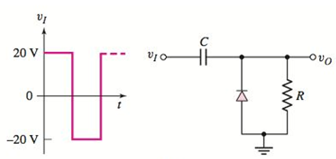
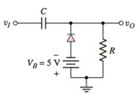
Figure P2.39
Expert Solution & Answer
Want to see the full answer?
Check out a sample textbook solution
Students have asked these similar questions
A circuit powered by a 20V DC supply has a 50kΩ resistor and 20 μ Capacitor connected in series. For this circuit determine the:a. Initial value of the current flowing? b. The time constant of the circuit? c. The value of current after 1 second of connection? d. The value of capacitor voltage 2 seconds after the connection?
What do you understand by Ferranti effect?
Subject Power Transmission and Distribution
Can you explain in detail? Thank you
HIGH VOLTAGE
Define Pschen’s theory related to breakdown of gaseous insulating material.
Chapter 2 Solutions
Microelectronics: Circuit Analysis and Design
Ch. 2 - Repeat Example 2.1 if the input voltage is...Ch. 2 - Consider the bridge circuit shown in Figure 2.6(a)...Ch. 2 - Assume the input signal to a rectifier circuit has...Ch. 2 - The input voltage to the halfwave rectifier in...Ch. 2 - Consider the circuit in Figure 2.4. The input...Ch. 2 - The circuit in Figure 2.5(a) is used to rectify a...Ch. 2 - The secondary transformer voltage of the rectifier...Ch. 2 - Determine the fraction (percent) of the cycle that...Ch. 2 - The Zener diode regulator circuit shown in Figure...Ch. 2 - Repeat Example 2.6 for rz=4 . Assume all other...
Ch. 2 - Consider the circuit shown in Figure 2.19. Let...Ch. 2 - Suppose the currentlimiting resistor in Example...Ch. 2 - Suppose the power supply voltage in the circuit...Ch. 2 - Design a parallelbased clipper that will yield the...Ch. 2 - Sketch the steadystate output voltage for the...Ch. 2 - Consider the circuit in Figure 2.23(a). Let R1=5k...Ch. 2 - Determine the steadystate output voltage O for the...Ch. 2 - Design a parallelbased clipper circuit that will...Ch. 2 - Consider the circuit shown in Figure 2.38, in...Ch. 2 - Consider the circuit shown in Figure 2.39. The...Ch. 2 - Repeat Example 2.11 for the case when R1=8k ,...Ch. 2 - The cutin voltage of each diode in the circuit...Ch. 2 - Prob. 2.12TYUCh. 2 - Consider the OR logic circuit shown in Figure...Ch. 2 - Consider the AND logic circuit shown in Figure...Ch. 2 - (a) Photons with an energy of hv=2eV are incident...Ch. 2 - Determine the value of resistance R required to...Ch. 2 - What characteristic of a diode is used in the...Ch. 2 - Prob. 2RQCh. 2 - Describe a simple fullwave diode rectifier circuit...Ch. 2 - Prob. 4RQCh. 2 - Prob. 5RQCh. 2 - Describe a simple Zener diode voltage reference...Ch. 2 - What effect does the Zener diode resistance have...Ch. 2 - What are the general characteristics of diode...Ch. 2 - Describe a simple diode clipper circuit that...Ch. 2 - Prob. 10RQCh. 2 - What one circuit element, besides a diode, is...Ch. 2 - Prob. 12RQCh. 2 - Describe a diode OR logic circuit. Compare a logic...Ch. 2 - Describe a diode AND logic circuit. Compare a...Ch. 2 - Describe a simple circuit that can be used to turn...Ch. 2 - Consider the circuit shown in Figure P2.1. Let...Ch. 2 - For the circuit shown in Figure P2.1, show that...Ch. 2 - A halfwave rectifier such as shown in Figure...Ch. 2 - Consider the battery charging circuit shown in...Ch. 2 - Figure P2.5 shows a simple fullwave battery...Ch. 2 - The fullwave rectifier circuit shown in Figure...Ch. 2 - The input signal voltage to the fullwave rectifier...Ch. 2 - The output resistance of the fullwave rectifier in...Ch. 2 - Repeat Problem 2.8 for the halfwave rectifier in...Ch. 2 - Consider the halfwave rectifier circuit shown in...Ch. 2 - The parameters of the halfwave rectifier circuit...Ch. 2 - The fullwave rectifier circuit shown in Figure...Ch. 2 - Consider the fullwave rectifier circuit in Figure...Ch. 2 - The circuit in Figure P2.14 is a complementary...Ch. 2 - Prob. 2.15PCh. 2 - A fullwave rectifier is to be designed using the...Ch. 2 - Prob. 2.17PCh. 2 - (a) Sketch o versus time for the circuit in Figure...Ch. 2 - Consider the circuit shown in Figure P2.19. The...Ch. 2 - Consider the Zener diode circuit shown in Figure...Ch. 2 - Consider the Zener diode circuit shown in Figure...Ch. 2 - In the voltage regulator circuit in Figure P2.21,...Ch. 2 - A Zener diode is connected in a voltage regulator...Ch. 2 - Consider the Zener diode circuit in Figure 2.19 in...Ch. 2 - Design a voltage regulator circuit such as shown...Ch. 2 - The percent regulation of the Zener diode...Ch. 2 - A voltage regulator is to have a nominal output...Ch. 2 - Consider the circuit in Figure P2.28. Let V=0 ....Ch. 2 - The secondary voltage in the circuit in Figure...Ch. 2 - The parameters in the circuit shown in Figure...Ch. 2 - Consider the circuit in Figure P2.31. Let V=0 (a)...Ch. 2 - Prob. 2.32PCh. 2 - Each diode cutin voltage is 0.7 V for the circuits...Ch. 2 - The diode in the circuit of Figure P2.34(a) has...Ch. 2 - Consider the circuits shown in Figure P2.35. Each...Ch. 2 - Plot O for each circuit in Figure P2.36 for the...Ch. 2 - Consider the parallel clipper circuit in Figure...Ch. 2 - A car’s radio may be subjected to voltage spikes...Ch. 2 - Sketch the steadystate output voltage O versus...Ch. 2 - Prob. D2.40PCh. 2 - Design a diode clamper to generate a steadystate...Ch. 2 - For the circuit in Figure P2.39(b), let V=0 and...Ch. 2 - Repeat Problem 2.42 for the circuit in Figure...Ch. 2 - The diodes in the circuit in Figure P2.44 have...Ch. 2 - In the circuit in Figure P2.45 the diodes have the...Ch. 2 - The diodes in the circuit in Figure P2.46 have the...Ch. 2 - Consider the circuit shown in Figure P2.47. Assume...Ch. 2 - The diode cutin voltage for each diode in the...Ch. 2 - Consider the circuit in Figure P2.49. Each diode...Ch. 2 - Assume V=0.7V for each diode in the circuit in...Ch. 2 - The cutin voltage of each diode in the circuit...Ch. 2 - Let V=0.7V for each diode in the circuit in Figure...Ch. 2 - For the circuit shown in Figure P2.54, let V=0.7V...Ch. 2 - Assume each diode cutin voltage is V=0.7V for the...Ch. 2 - If V=0.7V for the diode in the circuit in Figure...Ch. 2 - Let V=0.7V for the diode in the circuit in Figure...Ch. 2 - Each diode cutin voltage in the circuit in Figure...Ch. 2 - Let V=0.7V for each diode in the circuit shown in...Ch. 2 - Consider the circuit in Figure P2.61. The output...Ch. 2 - Consider the circuit in Figure P2.62. The output...Ch. 2 - Prob. 2.63PCh. 2 - Consider the circuit shown in Figure P2.64. The...Ch. 2 - The lightemitting diode in the circuit shown in...Ch. 2 - The parameters of D1 and D2 in the circuit shown...Ch. 2 - If the resistor in Example 2.12 is R=2 and the...Ch. 2 - Consider the photodiode circuit shown in Figure...Ch. 2 - Consider the fullwave bridge rectifier circuit....Ch. 2 - Design a simple dc voltage source using a...Ch. 2 - A clipper is to be designed such that O=2.5V for...Ch. 2 - Design a circuit to provide the voltage transfer...
Knowledge Booster


Learn more about
Need a deep-dive on the concept behind this application? Look no further. Learn more about this topic, electrical-engineering and related others by exploring similar questions and additional content below.Similar questions
- A) What is an emf of self-induction? a) when there is an induced emf in a circuit due to a change of current in the circuit itself b) when there is an induced emf in a circuit due to a change of current in an adjacent circuit (one within magnetic reach) B) Under what conditions of current flow is a self-induced ernf produced? a) whenever the circuit is energized b) whenever the circuit is de-energized c) whenever the amount of current flow in the circuit varies d) all of the above C) What is the direction of a self-induced emf in relation to any change in current? a) the same direction as the current flow that caused it b) the opposite direction as the current flow that caused it c) may be either "a" or "b" d) neither "a" nor "b" D). In an inductive circuit, does the inductance have any effect on the flow of a steady current? a) yes b) noarrow_forwardConsider two interconnected voltage sources connected by a line of impedance Z=jX, as shown in Figure 2.27. (a) Obtain expressions for P12 and Q12. (b) Determine the maximum power transfer and the condition for it toarrow_forwardDiscuss briefly the importance of renewable energy.arrow_forward
- Determine the transfer function for a tubular heat exchanger similar to the one shown in Figure 2.3 and described by the following differential equation: ** Please see attachmentarrow_forwardA lossy capacitor Cx, rated for operation of 5 kV, 50 Hz is represented by an equivalent circuit with an ideal capacitor Cp in parallel with a resistor Rp. Cp is 0.102 microF and Rp=1.25 Mohm. The power loss, and loss tangent of this lossy capacitor at rated voltage respectively ?arrow_forwardDiscuss Potential barriers of combined heat and power (CHP).arrow_forward
- 9. Write an equation to obtain the potential difference at point a with respect to point b, Vab? 10. What is the potential difference at point a with respect to point b, Vab?arrow_forwardPlease answer the following points in detail and rigorously. Instead ofresort to formulas, develop from basic principles (laws ofvoltages and currents, definition of electrical power, properties ofphasors, among others) a) Suppose that between the two terminals of an element there is a voltage v (t) and that through the terminal marked with a positive sign a current i (t). Show that if v (t) and i (t) are sinusoidal and are out of phase an angle θ, then the active power P which is consumed by this element is proportional to cosθ. b) How much is P for a pure inductor and how much for a capacitor pure? Does this make physical sense? c) When the power factor seen between two terminals is specified, Why is it necessary to indicate whether it is late or early? d) Show that the complex power consumed by two elements in parallel is the sum of the individual complex powers. After, repeat the procedure but for two elements in series. e) What meaning would you give to the P consumed by an…arrow_forwardPlease answer the following points in detail and rigorously. Instead ofresort to formulas, develop from basic principles (laws ofvoltages and currents, definition of electrical power, properties ofphasors, among others) d) Show that the complex power consumed by two elements in parallel is the sum of the individual complex powers. After, repeat the procedure but for two elements in series. e) What meaning would you give to the P consumed by an element? Which to Q? f) Suppose you know P and Q for a two-terminal element. What is the power factor of this element? When would i be in early and when behind? g) Suppose you know the equivalent resistance R and the reactance X equivalent of a two-terminal passive network. What is the factor power of red bliss? When would I be in advance and when in backwardness?arrow_forward
- Two long straight current-carrying wires are lined up parallel to one another in vacuum at a distancedCurrents of I1 and flow I2 through the wires, both in the same direction generating the field of B Delta f at a midpoint between themWrite down an expression for BM in terms of the currents running in each of the wires Assume vacuum permeability u= 1arrow_forwardA solid specimen of dielectric dielectric constant of 4.0, shown in the figure has an internal void of thickness 1mm. The specimen is 1cm thick and is subjected to a voltage of 80 kV(rms). If the void is filled with air and if the breakdown strength of air can be taken as 30 kV(peak)/cm, find the voltage at which an internal dischargearrow_forward2/ for the figure shown below find How much the potential Energy or the work Wa-b which s needed to move the test charge qo from point a to b along the radiallne if :qo= 2nc, 4= 5nc ra= 10 cm, b= 20, And from the value of the work find How much the Potential difference at g7 Testcharge g . moves fromat0b along radial line: fromg. Earrow_forward
arrow_back_ios
SEE MORE QUESTIONS
arrow_forward_ios
Recommended textbooks for you
 Power System Analysis and Design (MindTap Course ...Electrical EngineeringISBN:9781305632134Author:J. Duncan Glover, Thomas Overbye, Mulukutla S. SarmaPublisher:Cengage Learning
Power System Analysis and Design (MindTap Course ...
Electrical Engineering
ISBN:9781305632134
Author:J. Duncan Glover, Thomas Overbye, Mulukutla S. Sarma
Publisher:Cengage Learning
Why HIGH VOLTAGE DC power Transmission; Author: ElectroBOOM;https://www.youtube.com/watch?v=DFQG9kuXSxg;License: Standard Youtube License