
Videos
Let
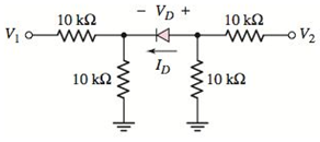
Figure P2.57
(a).
The values of
Answer to Problem 2.57P
Explanation of Solution
Given Information:
The given circuit is shown below.

Calculation:
Assuming the diode is in cutoff mode.
Applying voltage division rule:
The voltage across diode:
Hence, the diode is biased in reverse region. The assumption is correct and the value of diode current will be zero.
(b).
The values of
Answer to Problem 2.57P
Explanation of Solution
Given Information:
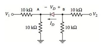
The given circuit is shown below.
Calculation:
Assuming the diode is in cutoff region.
Applying voltage division rule:
The voltage across diode:
Hence, the diode is biased in forward region. The assumption is incorrect.
Replacing the diode with its cut-in voltage:
The modified figure is:
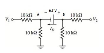
The node AB is a super node. Applying Kirchhoff’s current law at super node:
Adding equation 1 and 2:
From equation (1):
Applying Kirchhoff’s current law at node B:
(c).
The values of
Answer to Problem 2.57P
Explanation of Solution
Given Information:
The given circuit is shown below.

Calculation:
Assuming the diode is in cutoff mode.
Applying voltage division rule:
The voltage across diode:
Hence, the diode is biased in reverse region. The assumption is correct and the value of diode current will be zero.
(d).
The values of
Answer to Problem 2.57P
Explanation of Solution
Given Information:
The given circuit is shown below.

Calculation:
Assuming the diode is in cutoff region.
Applying voltage division rule:
The voltage across diode:
Hence, the diode is biased in forward region. The assumption is incorrect.
Replacing the diode with its cut-in voltage:
The modified figure is:

The node AB is a super node. Applying Kirchhoff’s current law at super node:
Adding equation 1 and 2:
From equation (1):
Applying Kirchhoff’s current law at node B:
Want to see more full solutions like this?
Chapter 2 Solutions
Microelectronics: Circuit Analysis and Design


- Since R1=4.51 Kohm, R2=1.19 Kohm R3=2.74Kohm R4=5.60Kohm VCC=23.00V and diode silicon in the circuit given in the figure, find the current passing through the diode in mAarrow_forwardWhile constructing a Bridge rectifier, the designer mistakenly has swapped the terminals of D3 as shown in the figure below, where • Diode D3 is damaged so that it is always open circuit regardless of the applied voltage. • vs(t) is a sinusoidal signal with a peak value (Vs = 5 V). • Diodes are modelled using the constant voltage model with VDO = 0.7 V • The ac line voltage has an rms value of 120 V and a frequency (f) = 60 Hz • The resistance RL = 10 kohm. a) Calculate the transformer turns ratio (N1/N2) if vs(t) is obtained from the secondary side of the transformer whose primary side is connected to the ac line voltage (which has a 120 V rms value). b) Plot in the same graph the input signal vs(t) and the output signal vout(t) (show all details including amplitudes, time instances, etc.) c) Calculate the rms values of the output signal vout(t). (hint: sin2 (x) = 0.5(1- cos(2x))) d) If a capacitor C = 3.58 µF is connected across R = 10 kohm, repeat (b) in a new graph e) With the…arrow_forwardWhile constructing a Bridge rectifier, the designer mistakenly has swapped the terminals of D3 as shown in the figure below, where • Diode D3 is damaged so that it is always open circuit regardless of the applied voltage. • vs(t) is a sinusoidal signal with a peak value (Vs = 5 V). • Diodes are modelled using the constant voltage model with VDO = 0.7 V • The ac line voltage has an rms value of 120 V and a frequency (f) = 60 Hz • The resistance RL = 10 kohm. a) Calculate the transformer turns ratio (N1/N2) if vs(t) is obtained from the secondary side of the transformer whose primary side is connected to the ac line voltage (which has a 120 V rms value). b) Plot in the same graph the input signal vs(t) and the output signal vout(t) (show all details including amplitudes, time instances, etc.) Please plot the graph. c) Calculate the rms values of the output signal vout(t). (hint: sin2 (x) = 0.5(1- cos(2x))) d) If a capacitor C = 3.58 µF is connected across R = 10 kohm, repeat (b) in a new…arrow_forward
- ⦁ Consider the below zener diode circuit and find the values of , , , . Use the constant voltage drop model which is shown is Figure 2. Show your solution steps clearly and explain them. The answers without solution steps will not be graded. Also, state your results in the sections below the circuits. ( = 0.1 )arrow_forwardApply each of diodeapproximations and determine:a. Current through D1b. Voltage across D2c. Voltage across R3 GIVEN: R1 = 2 kΩ, R2 = 1.2 kΩ, R3 = 6.8 kΩ E= 10 V D1: Si, rB = 2 Ω, rR = 220 kΩ D2: Si, rB = 5 Ω, rR = 560 kΩ DETERMING FIRST IF IT IS A FORWARD BIASED OR REVERSED BIASED THEN, SOLVE IN FIRST APPROXIMATION, SECOND APPROXIMATION AND THIRD APPROXIMATION SHOW THE CIRCUIT DIAGRAM IN EACH APPROXIMATIONarrow_forwarddiode zener a, DESIGN THE NETWORK IN THE FIGURE, TO KEEP, "VL" at 12 V for a variation in load (IL) from 0 to 200 mA, DETERMINE "Rs" and "Vz" b. determine "P2min" for the Zener diode from section aarrow_forward
- Question 3 a) The Fermi level of a solid-state body is the thermodynamic work required to add one electron to the body. The Fermi level does not include the work required to remove the electron from wherever it came from. With the aid of diagram discuss the importance of the Fermi Energy level, especially its relevance to electron flow in a pn-junction diode. b) Discuss the I/V characteristics curve of a practical Germanium diode and explain in detail how the forward and reverse are achieved. Support your explanation with a suitable circuit diagram with a voltage source and RC components connected across the p-n junctionarrow_forwardQ2 (b) Multiple diodes circuit is given in Figure (i) Identify the condition for Si and Ge diodes. (ii) Determine the current flowing into Si and Ge diodes. (iii) Calculate the output voltage, Voarrow_forwardAnswer the following questions according to the above. Remember Kirchhoff's laws when making your calculations in this question. a) According to the given graph, how many volts is the voltage value on it when this Zener diode is on a flat supply? b) According to the given graph, how many volts is the voltage value on this Zener Diode when it is on reverse supply? c) Calculate how many values V?−?? are when the zener current is 0 mA. D) Calculate how much the value of ??−?? is when the zener current is at its maximum value.arrow_forward
- DiodesFill in the blanks with the words belowcheck valve, conductance, convert, crystalline, impurities, infinite, galena, p–n junction, rectifying,resistance, selenium, semiconductor, switching circuits, tailored, temperature, threshold, two-terminal,unidirectionalA diode is a 1 ………………… electronic component that conducts current primarily in one direction(asymmetric 2 ………………..); it has low (ideally zero) 3 ……………… in one direction, and high (ideally4 ………………..) resistance in the other. A 5 ………….. diode, the most common type today, is a 6……….. piece of semiconductor material with a 7 ………………. connected to two electrical terminals. Avacuum tube diode has two electrodes, a plate (anode) and a heated cathode. Semiconductor diodes were thefirst semiconductor electronic devices. The discovery of crystals' 8 ……………… abilities was made byGerman physicist Ferdinand Braun in 1874. The first semiconductor diodes, developed around 1906, weremade of mineral crystals such as 9 ……………….. . Today,…arrow_forwardDesign the network of below to maintain V L at 12 V for a load variation (I L) from 0 mA to 200 mA. That is, determine R S and V Z. Determine P Z max for the Zener diode of part (a).arrow_forwardIn a 1-phase full wave bridge rectifier with Vs = Vm sin ωt, with R load & ideal diodes. The expression for the average value of the output voltage is 2Vm/π Select one: True Falsearrow_forward
 Introductory Circuit Analysis (13th Edition)Electrical EngineeringISBN:9780133923605Author:Robert L. BoylestadPublisher:PEARSON
 Delmar's Standard Textbook Of ElectricityElectrical EngineeringISBN:9781337900348Author:Stephen L. HermanPublisher:Cengage Learning
 Programmable Logic ControllersElectrical EngineeringISBN:9780073373843Author:Frank D. PetruzellaPublisher:McGraw-Hill Education
 Fundamentals of Electric CircuitsElectrical EngineeringISBN:9780078028229Author:Charles K Alexander, Matthew SadikuPublisher:McGraw-Hill Education
 Electric Circuits. (11th Edition)Electrical EngineeringISBN:9780134746968Author:James W. Nilsson, Susan RiedelPublisher:PEARSON
 Engineering ElectromagneticsElectrical EngineeringISBN:9780078028151Author:Hayt, William H. (william Hart), Jr, BUCK, John A.Publisher:Mcgraw-hill Education,