
Videos
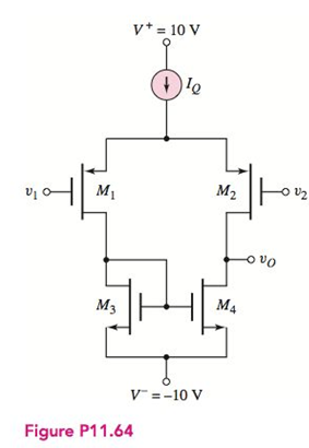
The differential amplifier in Figure P11.64 has a pair of PMOS transistors as input devices and a pair of NMOS transistors connected as an active load. The circuit is biased with
Want to see the full answer?
Check out a sample textbook solution
Chapter 11 Solutions
Microelectronics: Circuit Analysis and Design


- What is the term used to express the ability of a measuring system to maintain its standard performance? a) Zero Reliabilityb) Stabilityc) Sensitivityd) Linearityarrow_forwardUsing 741 op amp, design a suitable circuit to generate Binary Phase Shift Keyiing(BFSK) modulator. Design should perform in such a way that the BFSK output should contain a frequency of f1=2kHz when message signal is low and f2 =4kHz when the message signal is high. Take the frequency of message signal as 200Hz. Draw the clear circuit diagram and calculate the values of resistors and capacitors used.arrow_forwardIn the Mosfet circuit given below, R1+R2=50 kΩ, RD= 7.5 kΩ, VDD= 5V, VTP= -0.8 V, Kp= 0.2 mA/V2 is given. Calculate the ID current by determining the working region of the mosfet.arrow_forward
- Problem: Fx=(AB+CD+EF+G)' a. Draw its equivalent transistor circuit. b. Determine if the function has an Euler's path. please draw the equivalent Euler's path. C. Whether the circuit has a Euler's path or not, draw the stick diagram.arrow_forward(a) What are the Q-points for the transistors in the amplifier as shown if VDD = 9 V, VSS = 9 V, ISS = 40 μA, RSS = 1.25 MΩ, and RD = 300 kΩ? Assume Kp = 200 μA/V2, γ = 0.6 V0.5, 2φF = 0.6 V, and VTO = −1 V. (b) What are the differential-mode gain, common-mode gain, CMRR, and differential-mode and common-mode input resistances?arrow_forwardConsider the emitter follower in Figure 1 with VCC = 10V, I = 100 mA, and RL = 100Ω. (a) Find the power dissipated in Q1 and Q2 under quiescent conditions. (vO = 0V) (b) For a sinusoidal output voltage of maximum possible amplitude (neglecting VCEsat ), find the average power dissipation in Q1 and Q2. Also find the load power.arrow_forward
- Use a load-line analysis for the PMOS amplifier shown in Figure P11.24 to determine the maximum, minimum, and Q-point values of vo(t). The characteristics of the transistor are shown in Figure 11.9 on page 565.arrow_forwardIn the push-pull stage given (in the photo attached), IS1 = 5 × 10⁻¹⁷ A and IS2 = 8 × 10⁻¹⁷ A. Calculate the value of VB so as to establish a bias current of 5 mA in Q1 and Q2 (for Vout = 0). If the peak input swing is 2 V and RL = 8Ω : Calculate the small-signal voltage gain for Vout ≈ 0 Use the gain obtained in (i) to estimate the output voltage swing. Estimate the peak collector current of Q1 assuming that Q2 still carries 5 mAarrow_forward4--In the given circuit, n MOSFETs are used.Q1, Q2,….. Parameters of Qn MOS transistors Vt=1V, γ=0, λ=0,μnCox=200μA/V2 and (W/L)1=(W/L)2=….=(W/L)n=20a) VGS=?, ID=?, gm=?b) Find the input and output impedance.c) Find the voltage gain.arrow_forward
- If RB=12KΩ, RC=150Ω, VBB=7V, VCC=18V determine the IB, IC, IE and collector – emitter voltage in the circuit given below. The transistor has a gain (β) =150. Assume forward voltage drop of the BE junction is 0.7 V (Fig Q2 (d))arrow_forward) Draw a system block diagram of the main parts that integrate a complete ECG amplifier system with driven-right-leg noise compensation provision, and real-time ECG display on a PC screen.arrow_forwardConnect the elements given below as a BJT amplifier circuit with common emitter. BJT is BC547B terminals from left to right are named collector, base and emitter respectively. 9V battery as VCC source will be used. The audio signal obtained from the microphone will be connected to the circuit as the input signal. C0 at the outlet, CI at the inlet, CE is given as a bypass capacitor.arrow_forward
 Introductory Circuit Analysis (13th Edition)Electrical EngineeringISBN:9780133923605Author:Robert L. BoylestadPublisher:PEARSON
 Delmar's Standard Textbook Of ElectricityElectrical EngineeringISBN:9781337900348Author:Stephen L. HermanPublisher:Cengage Learning
 Programmable Logic ControllersElectrical EngineeringISBN:9780073373843Author:Frank D. PetruzellaPublisher:McGraw-Hill Education
 Fundamentals of Electric CircuitsElectrical EngineeringISBN:9780078028229Author:Charles K Alexander, Matthew SadikuPublisher:McGraw-Hill Education
 Electric Circuits. (11th Edition)Electrical EngineeringISBN:9780134746968Author:James W. Nilsson, Susan RiedelPublisher:PEARSON
 Engineering ElectromagneticsElectrical EngineeringISBN:9780078028151Author:Hayt, William H. (william Hart), Jr, BUCK, John A.Publisher:Mcgraw-hill Education,